
Apstra Test Drive
![]()
Apstra Fundamentals Lab Exercises - Junos
Completing these exercises is estimated to take approximately 90 minutes.
Exercise Obectives
This guide applies to the Juniper Customer Lab topology. Your Cloudlabs dashboard should have a banner similar to this:

The exercises in this lab allow you to explore the process of building a data center fabric with Juniper Apstra. By doing so, you will gain a fundamental understanding of the constructs and procedures necessary to get your pod operational. Then you will use various mechanisms to design a network and deploy it into the pod devices, making it a fully operational fabric. At the conclusion of this guide, you will have experienced Apstra participating in each phase of the network lifecycle.
The exercises will cover these apsects of the Apstra solution: [width##75%] |#### |- Device Management |- Resource Management |- Blueprint Deployment |- Multitenancy and Virtual Overlay Networks |- Configlets and Extending the DC Reference Architecture |- Intent-based Analytics |- Root Cause Identification |- Configuration Anomaly and Resolution |####
TIP: If this is your first time using the Cloudlabs environment, navigate to Home Page and view the Getting Started instructions.
‘’’
Before We Begin
Your Cloudlabs pods comes with virtual switches that are ready to be activated and added to your design. Establishing the pristine configuration and installation of agents has already been performed for you. In typical network deployments, devices are prepared manually and added to the system through the system GUI. Device preparation can also be automated via the use of Apstra’s built-in ZTP services. Details of Apstra ZTP are provided in the product documentation at this location: https://www.juniper.net/documentation/product/us/en/apstra/#cat##user_guides
How Apstra Manages Devices
As you progress through the lab steps, you will be defining models of common network constructs that are used to build fabric networks. The IBN approach uses these abstracted models to comprise your intended design. This approach gives Apstra the power to reliably deploy and modify complex infrastructure designs with astounding speed and precision.
The diagram below illustrates the constructs used by Apstra in modeling switch capabilities for use throughout the lifecycle of your network. For the sake of simplicity, Logical Devices and Interface Maps for our virtual switches have been defined for you, in advance. You will become familiar with how these items are applied in the upcoming exercises. You can explore these elements under the Devices>Device Profiles tabs and the Design>Logical Devices and Design>Interface Maps tabs in the server GUI.
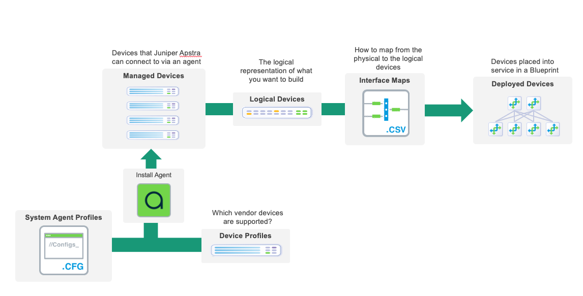
For more information on the elements in the diagram, refer to these links below;
Device profiles https://www.juniper.net/documentation/us/en/software/apstra4.1/apstra-user-guide/topics/topic-map/get-started.html#task_kgr_2jm_zsb
Logical Devices https://www.juniper.net/documentation/us/en/software/apstra4.1/apstra-user-guide/topics/topic-map/logical-devices-design.html#logical_devices_logical_device_overview
Interface Maps https://www.juniper.net/documentation/us/en/software/apstra4.1/apstra-user-guide/topics/topic-map/interface-maps-design.html#interface_maps_interface_map_overview
Let’s Get Started!
You can now move to the first exercise by using the navigation buttons at the bottom of the page. Otherwise, you may use the navigation bar on the left side of the page.
Enjoy the experience of building your first data center with Intent-Based Networking and Apstra
Resource Management
The resource management system in Apstra enables you to create resource pools for ASNs, VNIs and IP addresses. You can create them during the design phase or just before you need them during the build phase. When you assign resources to managed devices in your network (Blueprint), Apstra pulls them automatically from the pool you specify. In cases where you need to assign a specific network identifier you have the option of assigning a resource manually.
Create an IP Pool
The IP pool that we’ll create here is for you to see how easy it is to define resource pools. There are a number of pools needed for the exercises that have already been created for you. So, we won’t be using this particular one in the construction of the lab.
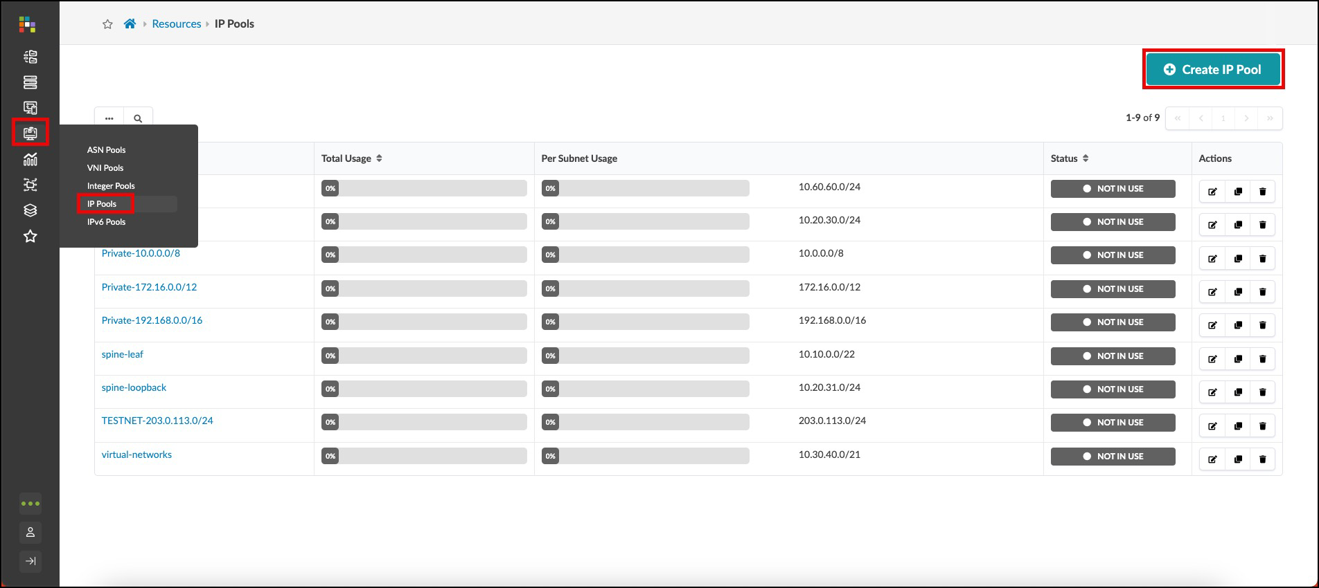
. Navigate to Resources > IP Pools and click Create IP Pool. [%hardbreaks]
[%hardbreaks] . You can create an IP pool with one or more ranges. Ours will have two ranges. Enter values as shown in the table below. Tags is an optional field for filtering and grouping. + .Table IP Pool Values [cols##”,”,options##”header”,stripes##hover] [width##75%] |#### |IP Pool |Value |Name |[.emphasis]#apstra#-pool |Subnet |4.0.0.0/24 |Add a subnet |[.emphasis]#click# Add a subnet |Subnet |4.0.1.0/24 |####
. Click Create to create the pool and return to the list view. The status bars for each resource pool give you a clear view of usage and indicate when you might need to replenish a pool with more resources.
TIP: Hovering over a status bar shows the number of resources used out of the total number of resources in that range.
Create ASN Pool
The procedure for creating ASN pools is similar to the one for creating IP pools. When we need an ASN later, we’ll have Apstra assign one from the pool that we’re about to create.
. Navigate to Resources > ASN Pools and click Create ASN Pool. . Enter values as shown in the table below. + .Table ASN Pool Values [cols##”,”,options##”header”,stripes##hover] [width##75%] |#### |ASN Pool |Value |Name |vpod-evpn-asn-pool |Ranges |100 - 1000 |#### . Click Create to create the pool and return to the list view.
Templates
Templates are where we assemble the building-blocks we have constructed so far, on our journey to create a Blueprint. We have already put our devices into Racks. Now we will create a Template, where we place our Racks and other selections on how our network will operate. This is the template that we will use when it’s time to turn all our preparations into an operating fabric.
Create Template
Let’s create the Template we will use to create our Blueprint.
. Navigate to Design > Templates and click Create Template. +

. In the Common Parameters section, enter/select values as shown in the table below. + .Table Template Common Parameters Values [cols##”,”,options##”header”,stripes##hover] [width##75%] |#### |Common Parameters |Value |Name |[.emphasis]#apstra_junos# |Type |RACK BASED |#### + . In the Policies section, select values as shown in the table below. + .Table Template Policies Values [cols##”,”,options##”header”,stripes##hover] [width##75%] |#### |Policies |Value |ASN Allocation Scheme (spine) |Unique |Overlay Control Protocol |MP-EBGP EVPN |#### + . In the Structure section, enter/select values as shown in the table below. Notice that as you enter information the topology preview on the right changes accordingly. The rack types we are specifying here were created ahead of time for you. They are the same as the ones you created with your own name. + .Table Template Structure Values [cols##”,”,options##”header”,stripes##hover] [width##75%] |#### |Structure |Value |Rack Types |apstra-esi (1x10 Gbps links to spines) |Number of Racks (to the right of rack type) |1 |Rack Types |[.emphasis]#click# Add racks |Rack Types |apstra-single (1x10 Gbps links to spines) |Number of Racks |1 |Spine Logical Device |virtual-7x10⁻¹ |(Spine) Count |2 |Links per Superspine Count |[.emphasis]#leave as is# |Link to Superspine Speed |[.emphasis]#leave as is# |#### + . Click Create to create the template and return to the list view. To see template details, click its name in the list. Click the Show Links? box to see where the connections will occur. This is how your completed template should appear:

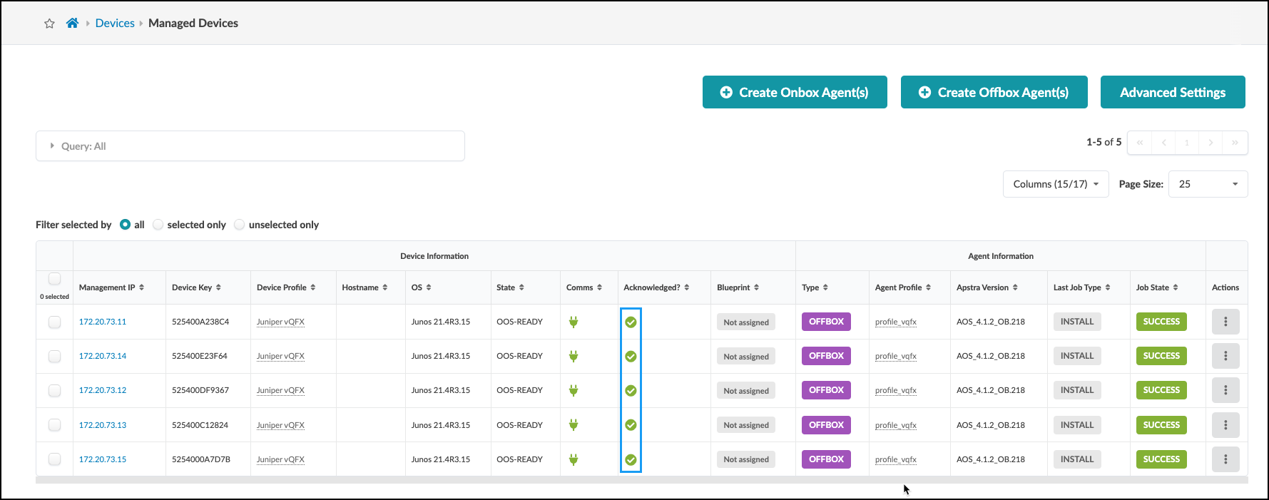
. Click the checkbox in the column header to select all five devices. A row of icons appears above the list for tasks that can be performed on the devices. . Click the Acknowledge selected systems button (first one on the left), then click Confirm to acknowledge them and return to the list view. The fields in the Acknowledged column change to green check marks indicating that the devices are ready to be managed by Apstra. +

. When all devices are acknowledged, your Managed Devices table should look similar to this. Note that your management IP addresses will be different from those shown. +
Blueprints
Now, you will take the elements that we created in previous sections (and some others that were predefined for you) and bring them together to create a blueprint. Then you will configure individual resources for various elements in the Staging tab. Some elements require resource assignments from pools to complete the configurations. This exercise takes you through the necessary assignments. As these are added, Apstra extracts what is needed from the pool assignments and ensures that all required resources are properly allocated. These details are validated to verify they are in compliance with the design intent before any configurations are performed on the devices. Let’s begin the blueprint creation now.
Create Blueprint
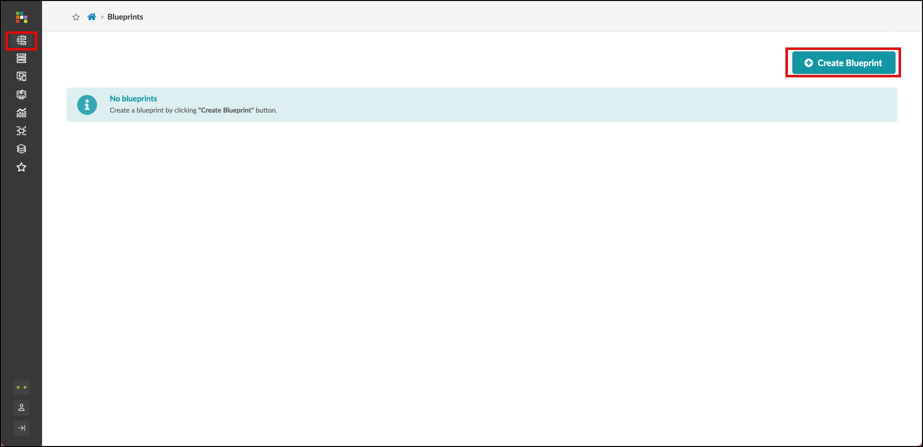
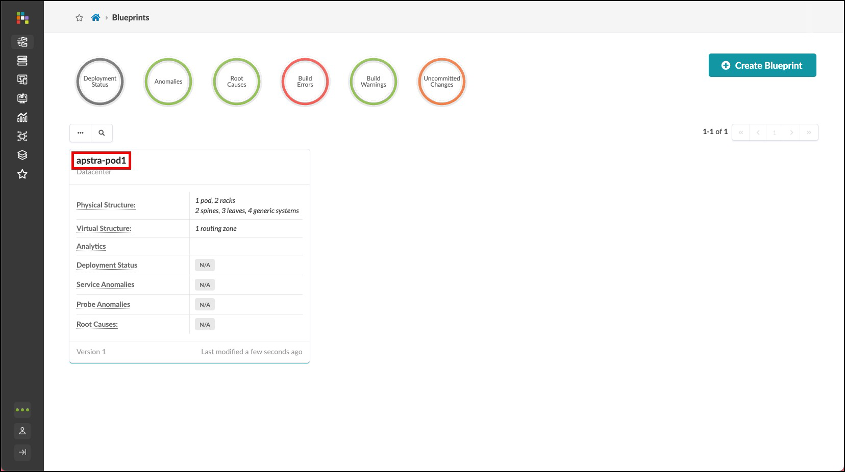
. Click Blueprints, then click Create Blueprint. +
. Name the blueprint apstra-pod1 or you may replace apstra with your own name, if you like. . From the template drop-down list, select apstra. A preview of the blueprint’s intent appears. . Click Create to create the blueprint and return to the blueprint summary view. For a moment, you will see Apstra ‘scaffolding’ the blueprint . Once complete, click the blueprint name to see its dashboard. This is where you can check the overall health of the network and quickly see any anomalies. But, before we can see any information on the dashboard, we’ll need to complete our build-out of the blueprint and deploy it. Let’s get started by clicking on the blueprint you have just created. +
Assign Resources
You’ll notice that there are red indicators showing where assignments are needed. These are places where assignments are necessary to complete the definitions and prepare for deployment. Let’s begin these assignments.
. From the blueprint, navigate to Staged > Physical > Build > Resources. +
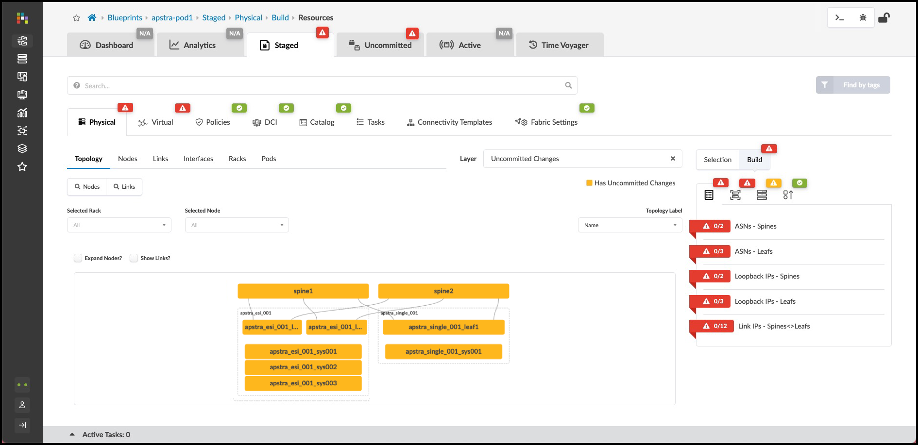
. Click the red status indicator next to one of the required resources, then click the Update assignments button to see available resource pools. +
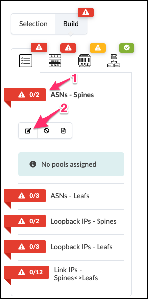
. Select the pool as specified in the table below for the required resource that you are assigning: + .Table Pool Resources [cols##”,”,options##”header”,stripes##hover] [width##85%] |#### |Resource Requirement |Resource Pool |ASNs - Spines |vpod-evpn-asn-pool (You created this one.) |ASNs - Leafs |vpod-evpn-asn-pool |Loopback IPs - Spines |spine-loopback (This was created for you.) |Loopback IPs - Leafs |leaf-loopback (This was created for you.) |Link IPs - Spines <>Leafs |spine-leaf (This was created for you.)
|####
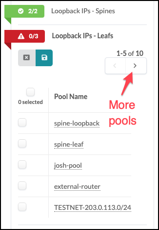
If you don’t see the required pool, you may need to click the directional arrow to see additional pools.
[start##4]
. Click the Save button. When the resource has been
successfully assigned, the red status indicator turns green.
+
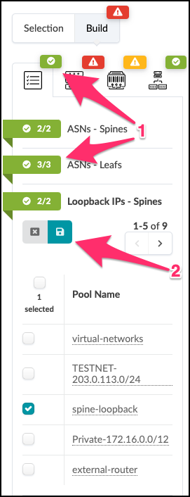
. Repeat the steps for each resource requirement.
Assign Interface Maps and Perform Our First Commit
. To the right of the Resources tab, select the Device Profiles tab. +
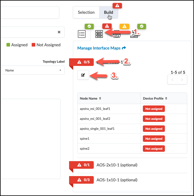
. Click the red status indicator next to virtual-7x10⁻¹, then click the Change interface maps assignment button. . Select interface maps for each device as shown in the table below. + .Table Interface Map Assignment Values [cols##”,”,options##”header”,stripes##hover] [width##85%] |#### |Name |Interface Map |evpn_esi_001_leaf1 |Juniper_vEX__slicer-7x10⁻¹ |evpn_esi_001_leaf2 |Juniper_vvEX__slicer-7x10⁻¹ |evpn_single_001_leaf1 |Juniper_vEX__slicer-7x10⁻¹ |spine1 |Juniper_vEX__slicer-7x10⁻¹ |spine2 |Juniper_vEX__slicer-7x10⁻¹ |#### + . Click Update Assignments to assign the device models and return to the build page. After a moment the red status indicator turns green indicating that the assignment was successful.
Assign System IDs
. To the right of the Device Profiles tab, select the Devices tab. + . Click the yellow status indicator next to Assigned System IDs, then click the Change System IDs assignments button +
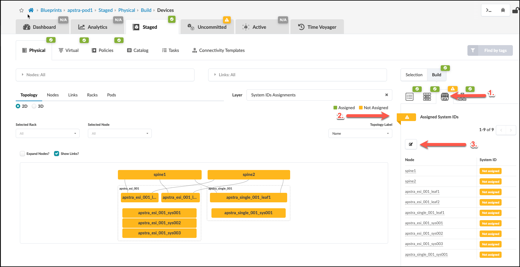
. Select values as shown in the table below replacing
[.emphasis]#yoursubnet## with the subnet for your own lab. You can
find it on your CloudLabs portal, and it will also be in the
System ID drop-down lists.
+
.Table System ID Values
[cols##”,”,options##”header”,stripes##hover]
[width##85%]
|####
|Hostname |Value
|spine1 |172.20.yoursubnet.11
|spine2 |172.20.yoursubnet.12
|evpn_esi_001_leaf1 |172.20.yoursubnet.13
|evpn_esi_001_leaf2 |172.20.yoursubnet.14
|evpn_single_001_leaf1 |172.20.yoursubnet.15
|####
+
 +
+
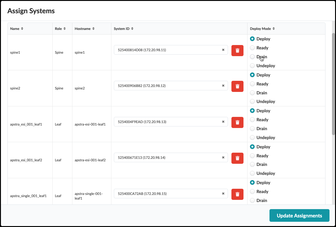
. Ensure that each system is set to Deploy mode while noting the last octet of each device’s IP address. They are not contiguous. Click Update Assignments to assign the System IDs and you are returned to the Build page. If you had any difficulty making these assignments, make sure you performed the interface map assignments correctly (previous step). Now, let’s commit everything we have done so far into the new blueprint.
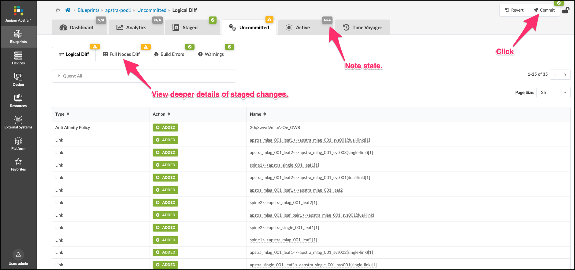
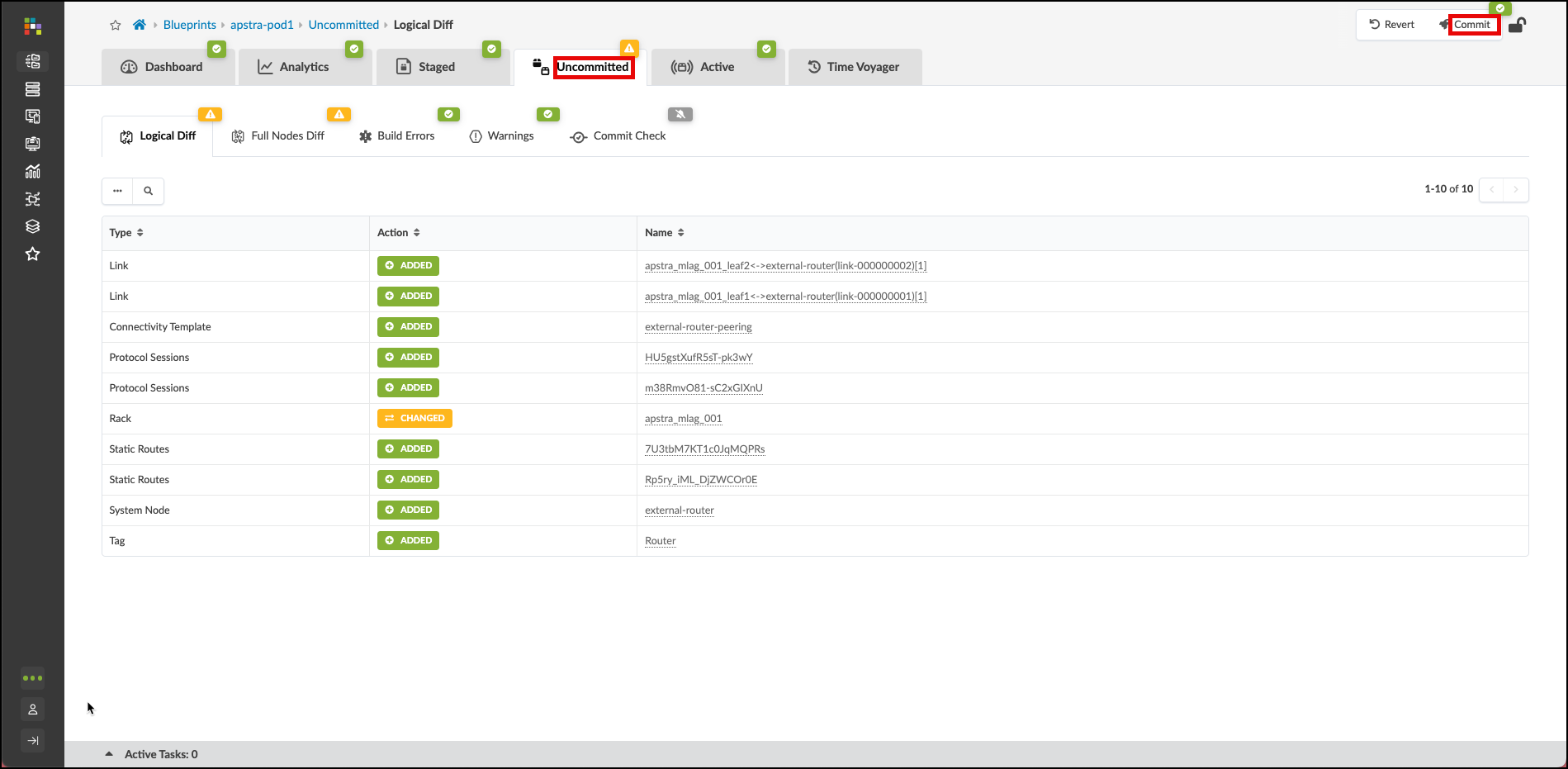
. Click the Uncommitted tab and see all the elements that are staged. The information you see is logical difference in the blueprint state since the last Commit was made. Since this is the very first one, this view shows us everything we have added since we instantiated the blueprint from the template. You can see even more details about the staged changes by clicking the Full Nodes Diff tab. Have a look around this screen to become familiar with how things appear when changes are complete and ready to be pushed to the Active network.
. After you have looked about, click the Commit button in the upper right.
+
 +
. Pressing Commit brings up a screen where you can place a description of the changes. Notes and details of the stages changes should be entered to describe what is being added to the blueprint. The more descriptive you are, the better it will be when you wish to move between fabric snapshots using the Time Voyager feature.
+
+
. Pressing Commit brings up a screen where you can place a description of the changes. Notes and details of the stages changes should be entered to describe what is being added to the blueprint. The more descriptive you are, the better it will be when you wish to move between fabric snapshots using the Time Voyager feature.
+
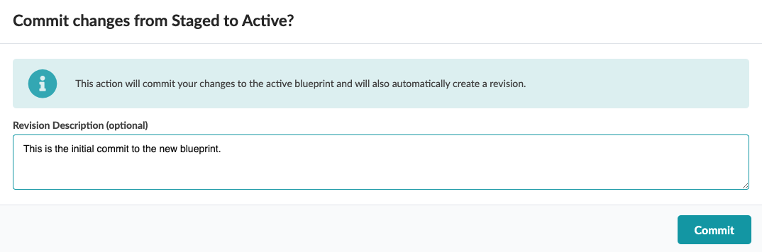 +
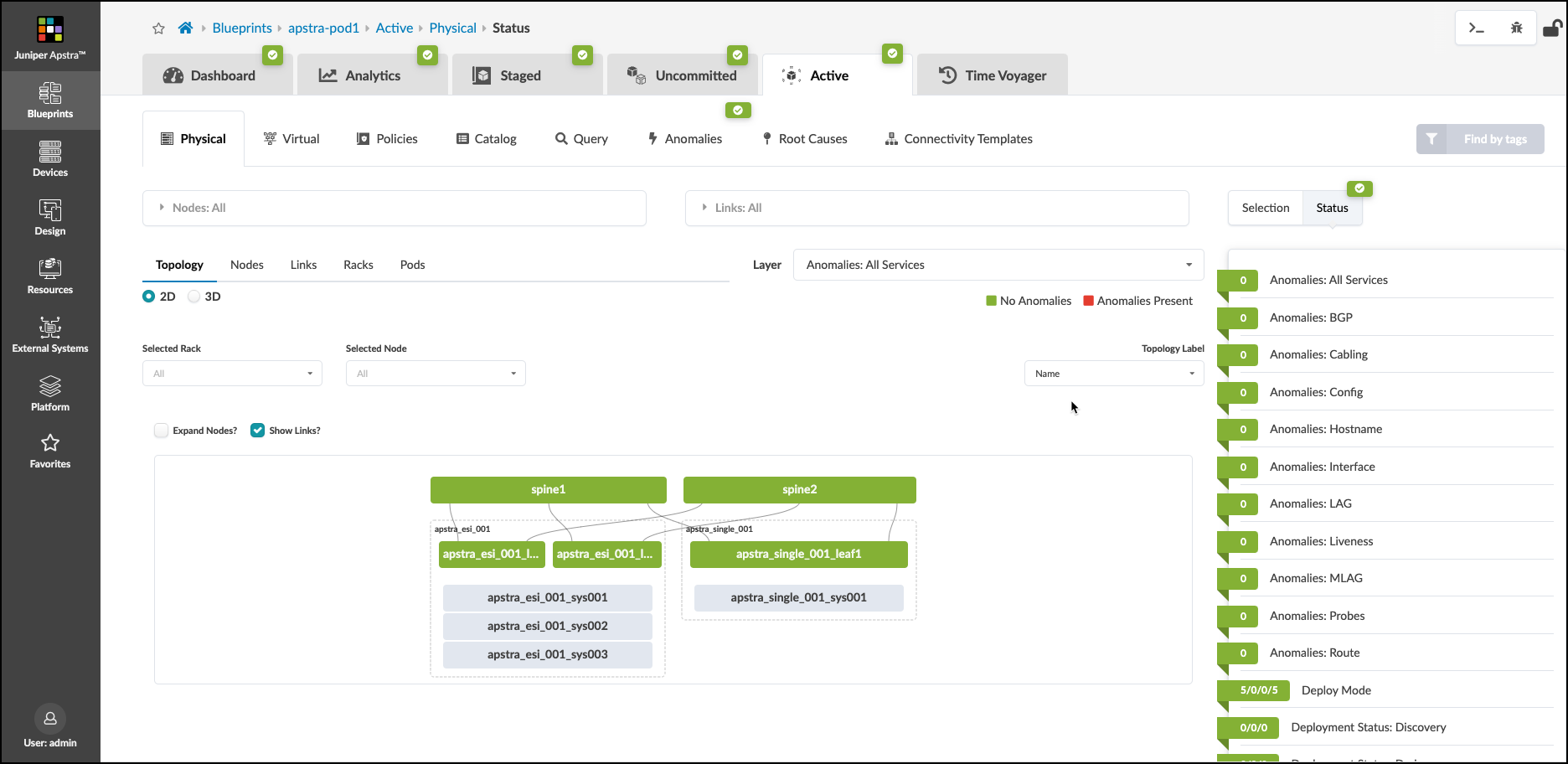
. Once the description is entered, press the Commit button and watch as the Active network is configured. This will take some time. You can enter the Active to watch the network come to life. Over time, the objects will turn green and the anomalies will dissipate. Be patient as the agents configure each device and telemetry begins to flow. Once everything turns green, you are ready to move to the next step.
+
. Once the description is entered, press the Commit button and watch as the Active network is configured. This will take some time. You can enter the Active to watch the network come to life. Over time, the objects will turn green and the anomalies will dissipate. Be patient as the agents configure each device and telemetry begins to flow. Once everything turns green, you are ready to move to the next step.
This is how your network should appear before moving on to the next exercise, where we add the external connections to the fabric.
Configure External Router Node
The data center Reference Architecture provides the ability model external connectivity in a very flexible and detailed manner. This exercise walks you through defining the External Router, its links and the details of BGP peering in the Default VRF. Later, we will build on this by adding reachability between our overlay networks and the external world.
Add External Generic
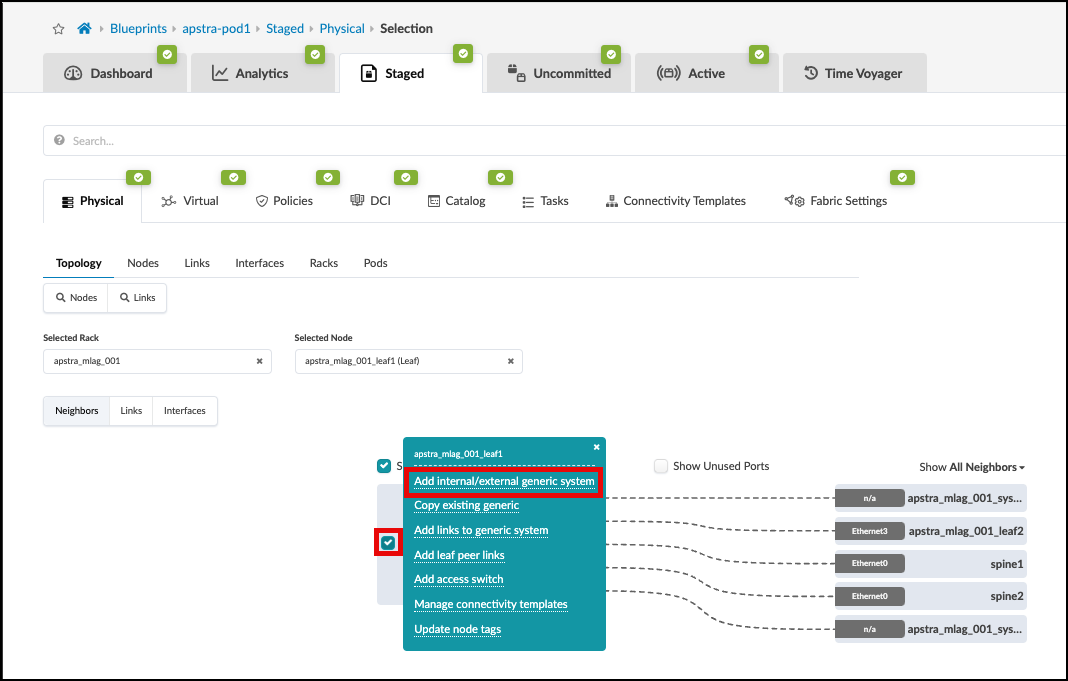
. Navigate to Staged > Physical > Topology and select
the leftmost switch in the apstra_esi_001 rack. You will move to a new view of the leaf1 switch.
+
 . On the leaf1 switch, click the box left of the device’s name. When the menu appears, click Add internal/external generic system.
+
. On the leaf1 switch, click the box left of the device’s name. When the menu appears, click Add internal/external generic system.
+
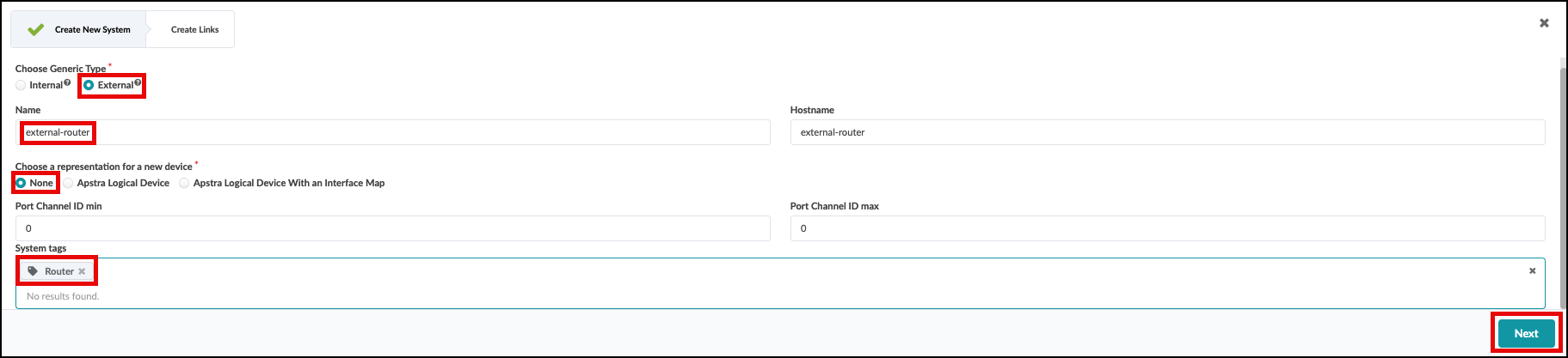
 . Click on the Add external generic on the menu that appears.
. On the next screen that appears, it is important to select None for “Choose a representation for a new device” as the first step. Performing the steps out-of-order will cause the “Label” and “Hostname” fields to require re-entry.
. Second enter “external-router” in the Label and “Hostname” fields. Add a tag named “Router” to the tags
field. Lastly, click Next to proceed to the next page.
+
. Click on the Add external generic on the menu that appears.
. On the next screen that appears, it is important to select None for “Choose a representation for a new device” as the first step. Performing the steps out-of-order will cause the “Label” and “Hostname” fields to require re-entry.
. Second enter “external-router” in the Label and “Hostname” fields. Add a tag named “Router” to the tags
field. Lastly, click Next to proceed to the next page.
+
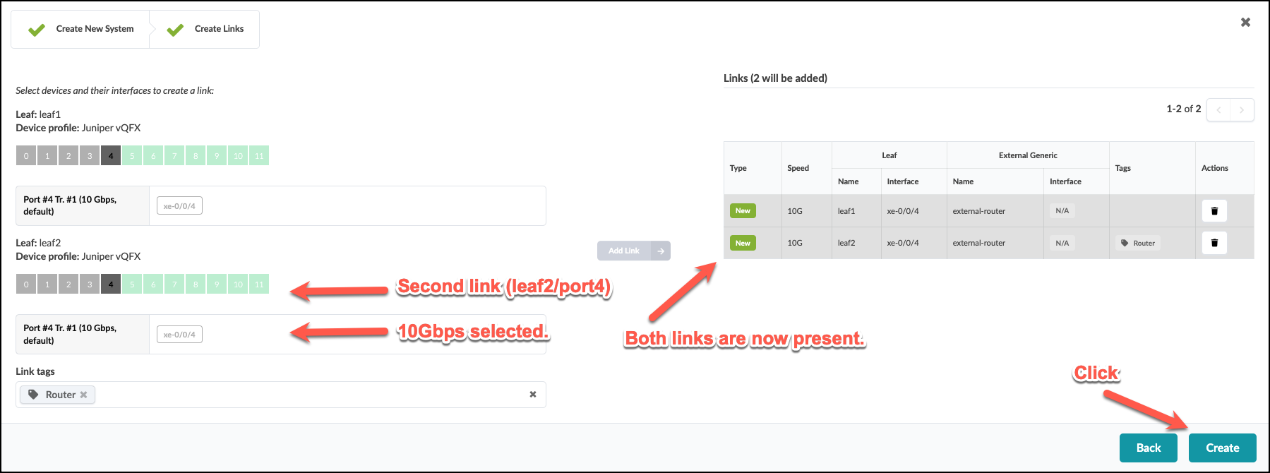
. You are presented with a port layout for each switch in the rack. Click to select the first available port for the first switch, click the “10Gbps” transformation. Then add a new tag named “Router” below in the “System Tags” sec)[JAB_create_juniper_external_router_links1.png]
. If the steps are successful, the Add Link button in the center
of the window will turn green. Click it to add the link to the
Links list on the right.
. Repeat the steps above for the second switch. Your screen should look like this:
+
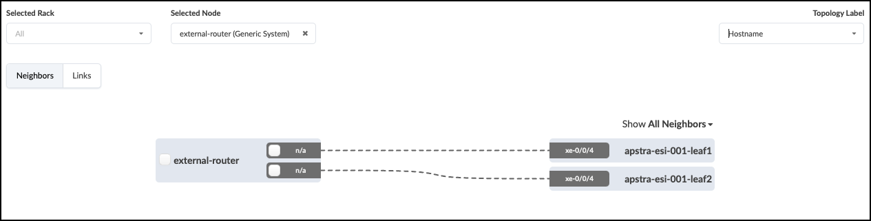
. When everything looks correct, click Create to finish the creation of the external router link. This process stages the addition of the external router, and it’s link details to the Blueprint. In the staged view, you will now see your external router depicted with a link to both switches in the apstra-esi-001 rack.
+
Configure Default VRF Peering
We have given the system details about how we wish to physically connect the leaf pair to the external router. Now we need to tell Apstra what kind of layer 3 characteristics need to be applied to the links. This information is placed into an object known as a Connectivity Template (CT). A CT contains the architectural details necessary for creating an IP Link with BGP peering between the leaf pair and the external router. Let’s begin the process of creating our template.
. Navigate to Staged > Connectivity Templates and click
Add Template.
+
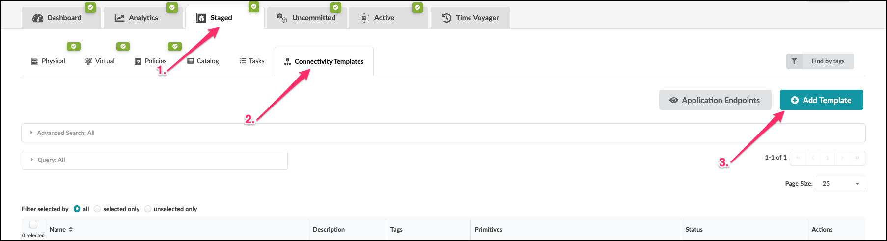
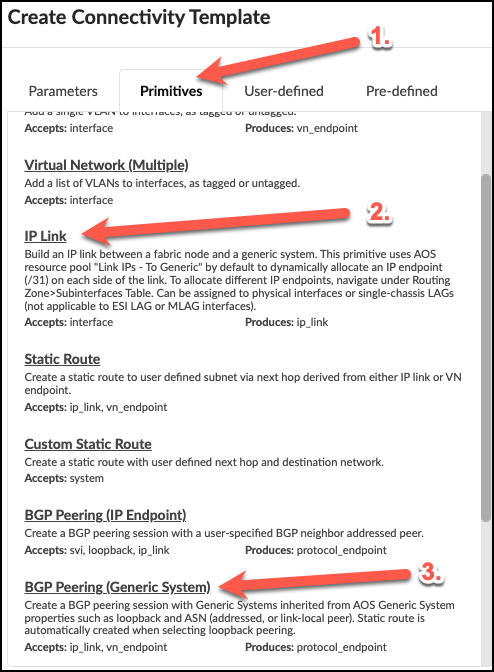
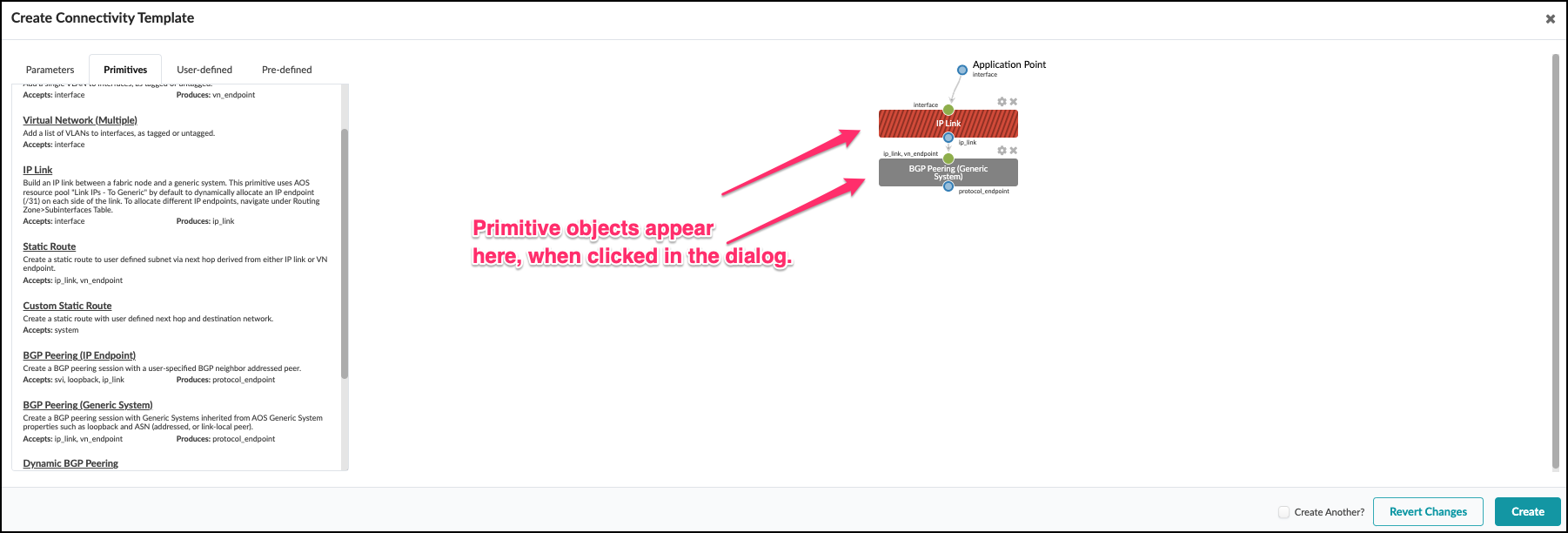
. In the dialog that opens, click the Primitives tab then click IP LInk to add the primitive to the template. You will see this object appear in the area to the right of the dialog. Now, click BGP Peering (Generic System) to add it to the IP link primitive in the template. The object will appear to the right, under the IP Link. +
. This view shows your entries creating the objects in your CT.
+
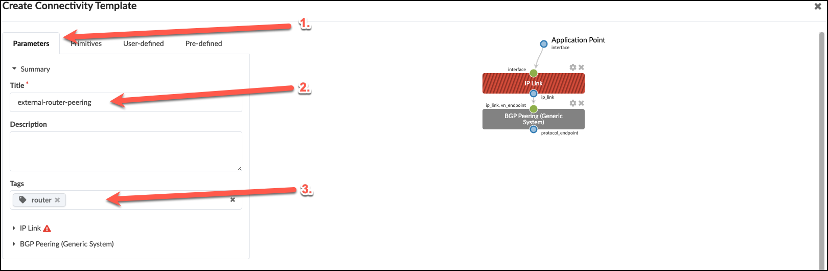
. Now, select the Parameters tab to edit the default values. + .Table Configure Connectivity Template [cols##”,”,options##”header”,,stripes##hover] [width##75%] |#### |Property |Value |Title |external-router-peering |Tag |Router |####
 +
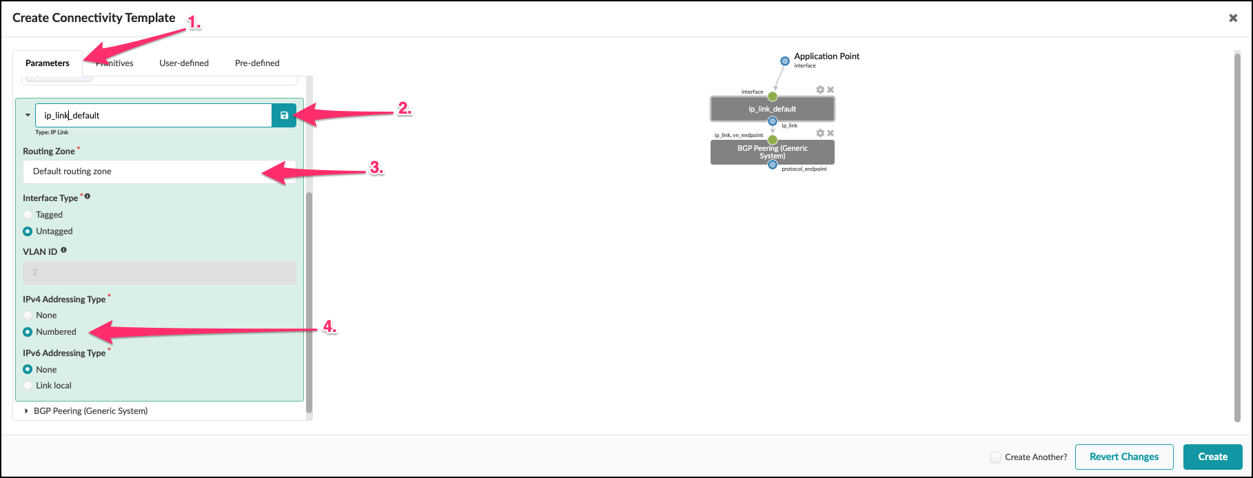
. Click the IP Link arrow to edit the parameters with the values shown below.
+
+
. Click the IP Link arrow to edit the parameters with the values shown below.
+
.Table IP Link Parameters
[cols##”,”,options##”header”,,stripes##hover]
[width##75%]
|####
|Property |Value
|IP Link (hover and select the Edit pencil) |ip_link_default (click save icon)
|Routing Zone |Default routing zone
|Interface Type |Untagged
|####
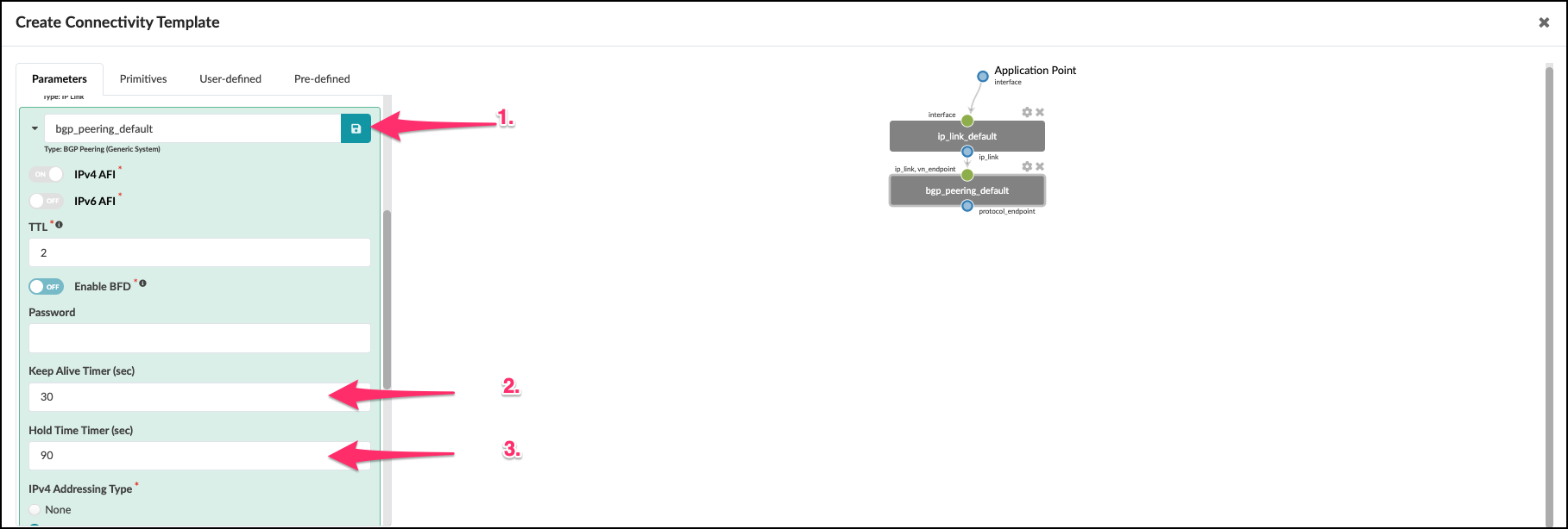
. Click the BGP Peering arrow to edit the parameters with the values shown. + .Table Configure BGP Peering (Generic System) Parameters [cols##”,”,options##”header”,,stripes##hover] [width##75%] |#### |Property |Value |BGP Peering (hover and select the pencil icon to edit title) |bgp_peering_default (click the Save icon)
|Keep Alive Timer (sec) |30
|Hold Time Timer (sec) |90
|####
+
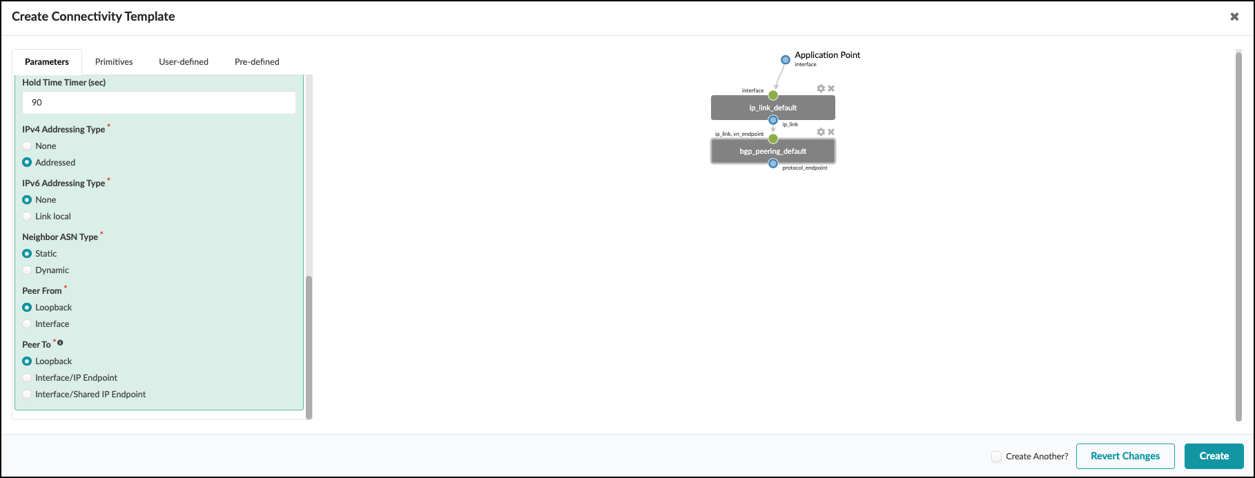
 . Scroll down a bit to see the rest of the settings. The default values here are appropriate for our CT.
+
. Scroll down a bit to see the rest of the settings. The default values here are appropriate for our CT.
+
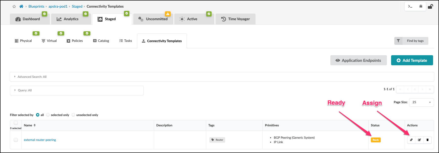
 . Click Create. If everything is defined properly, the connectivity template is listed and the
status column shows Ready. Now click the Assign icon to open the view where we associate the CT to the external-router links.
+
. Click Create. If everything is defined properly, the connectivity template is listed and the
status column shows Ready. Now click the Assign icon to open the view where we associate the CT to the external-router links.
+
 +
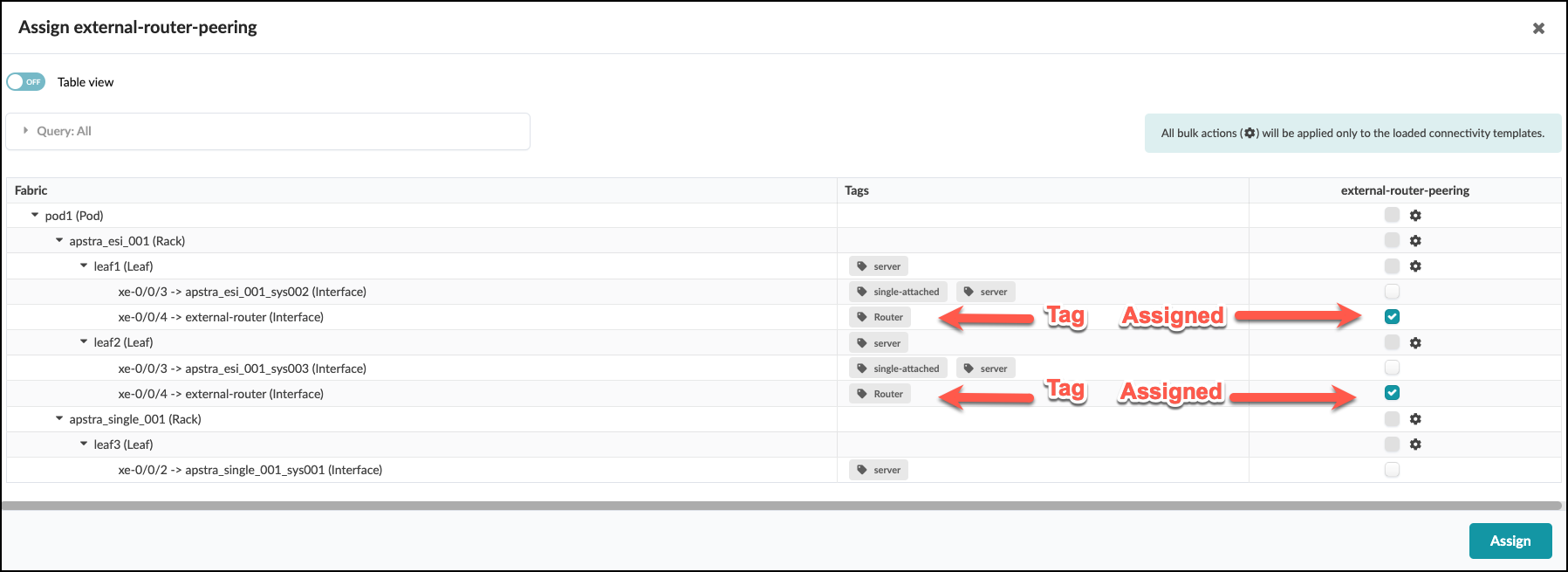
. In the Assign external-router-peering window check the box for each switch interface assigned to the external-router. Notice
the “Router” tag next to each of these interfaces. Tags are very handy for identifying objects and are used more in depth later. After checking the two boxes, click the Assign button.
+
+
. In the Assign external-router-peering window check the box for each switch interface assigned to the external-router. Notice
the “Router” tag next to each of these interfaces. Tags are very handy for identifying objects and are used more in depth later. After checking the two boxes, click the Assign button.
+
 . After Assign is clicked, the blueprint view will show new information. First, note that the Connectivity Template shows that it is Assigned on 2 endpoints. Next, there are some new red indicators that we must address.
+
. After Assign is clicked, the blueprint view will show new information. First, note that the Connectivity Template shows that it is Assigned on 2 endpoints. Next, there are some new red indicators that we must address.
+
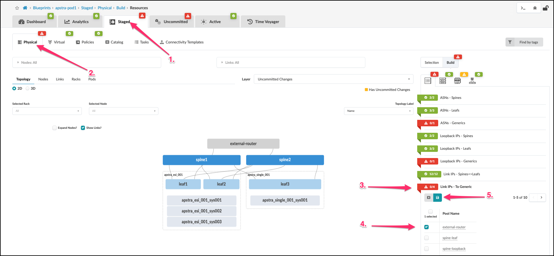
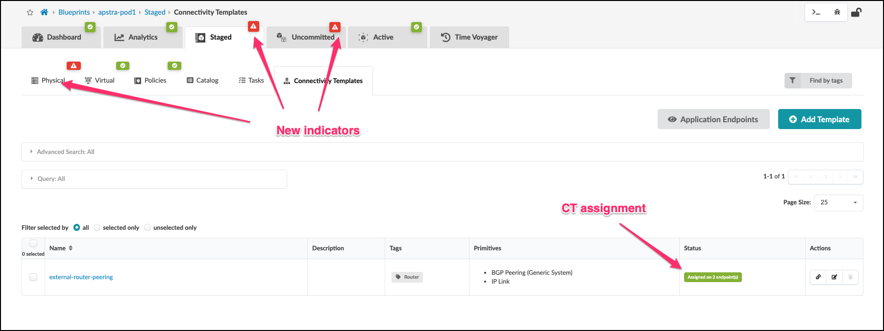 . The creation and assignment of our CT to the external router links results in red indications where additional resource assignments are needed. First, navigate to Staged > Physical > Build > Resources table. Click Link IPs - To Generic and assign the external-router IP address pool. Once you have clicked the IP pool, click the diskette icon to save your selections.
+
. The creation and assignment of our CT to the external router links results in red indications where additional resource assignments are needed. First, navigate to Staged > Physical > Build > Resources table. Click Link IPs - To Generic and assign the external-router IP address pool. Once you have clicked the IP pool, click the diskette icon to save your selections.
+
 . Our blueprint now shows that Link IPs-To Generic is now green. But we still have some red indicators that require our attention.
+
. Our blueprint now shows that Link IPs-To Generic is now green. But we still have some red indicators that require our attention.
+
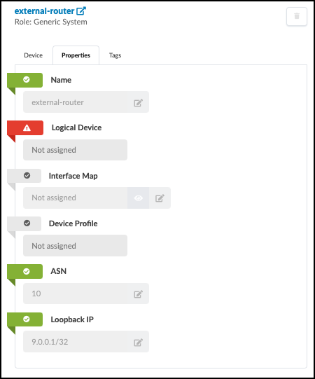
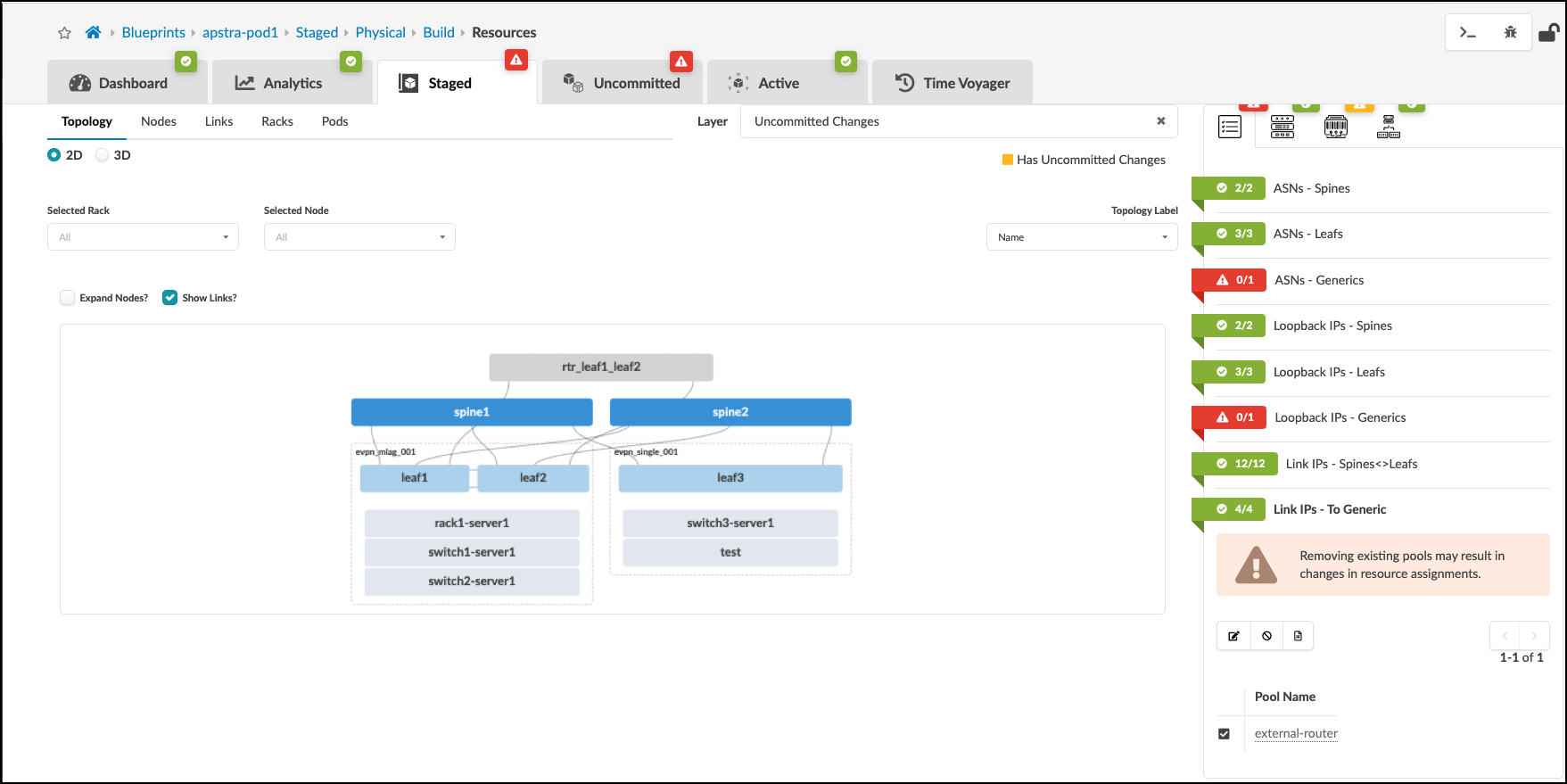 . Now, click the external-router object. Select the Properties tab. This will change to the view where we will assign the router’s ASN value to 10. Then, we will assign the router’s loopback IP with 9.0.0.1/32. Click the Edit icon for each field and assign the appropriate value. Note that Logical Device will remain red and unassigned since we selected None earlier when defining our External Router links.
. The external-router Properties view will now look like this image.
+
. Click the X to deselect the external router in the Selected Node field. This will move the view up one level.
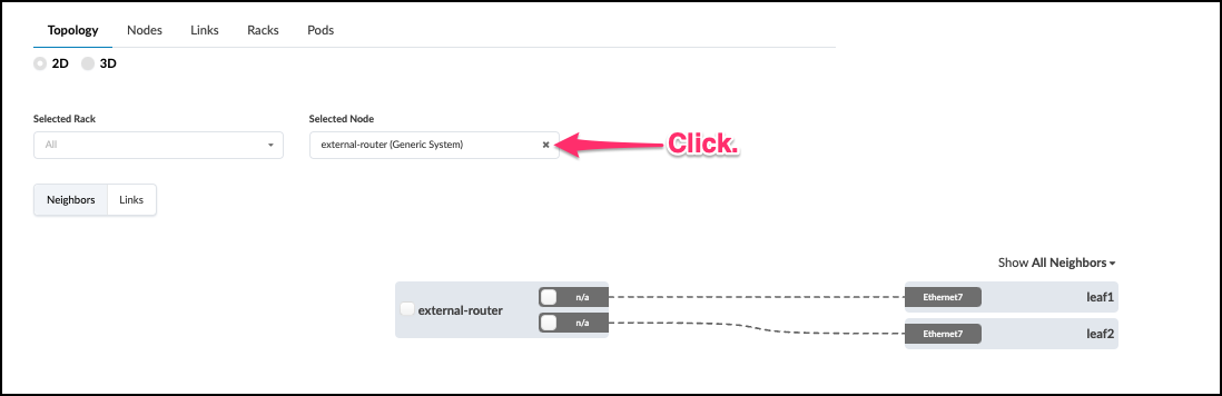
. Now that we have completed the definition of our external router and its properties, we are ready move on and commit all of our staged input into the Blueprint. Our networking intentions will soon come to life.
Deploy Update to the Blueprint
. Click Uncommitted to see the work we’ve done since our first Commit. We have created an
external router, links and a Connectivity Template to support VRF peering. Now, it’s time to deploy
these staged elements to the blueprint.
+
. Click the Commit button and enter the description
“Milestone 2”. Then click Commit on the lower right to push the additions to your blueprint.
. Now, we must perform an additional step for Cloudlabs to update the external router. Apstra doesn’t manage the configuration on this device, so this enables default VRF peering between this router and the leaf pair.
+
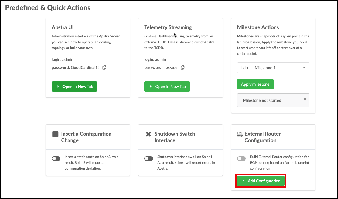 +
. Click Add Configuration, enter
apstra-pod1 or yourname-pod1 (this value must match what you named your blueprint) and click
Submit. The external router will automatically be configured.
+
. Click Add Configuration, enter
apstra-pod1 or yourname-pod1 (this value must match what you named your blueprint) and click
Submit. The external router will automatically be configured.
NOTE: We will perform this Add Configuration procedure again at the conclusion of the next exercise. This sets the External Router’s interfaces to the appropriate settings for peering with each Routing Zone.
When your screen matchs this view, you have reached Milestone 2.
![]()
Multi-tenancy
Virtual Networks
Virtual networks (VN) are collections of L2 forwarding domains. In an Apstra-managed fabric, a virtual network can be constructed using either VLANs or VXLANs.
Routing zones are created in a template where MP-EBGP EVPN is configured as the overlay control protocol. Only inter-rack virtual networks can be associated with routing zones. For a virtual network with Layer 3 SVI, the SVI will be associated with a VRF for each routing zone isolating the virtual network SVI from other tenants. This lab is for an MP-EBGP EVPN datacenter, so we’ll be using VXLAN.
Create Routing Zone
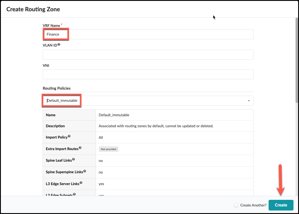
. From the blueprint, navigate to Staged > Virtual >
Routing Zones and click Create Routing Zone.
 . Name the new RZ Finance and select the Default Immutable Routing policy.
 +
+
. Assign the EVPN L3 VNIs pool as shown:
+
.Table Assign Resources to Routing Zone
[cols##”,”,options##”header”,stripes##hover]
[width##75%]
|####
|Resource Requirement |Resource Pool
|EVPN L3 VNIs |evpn-vni
|####
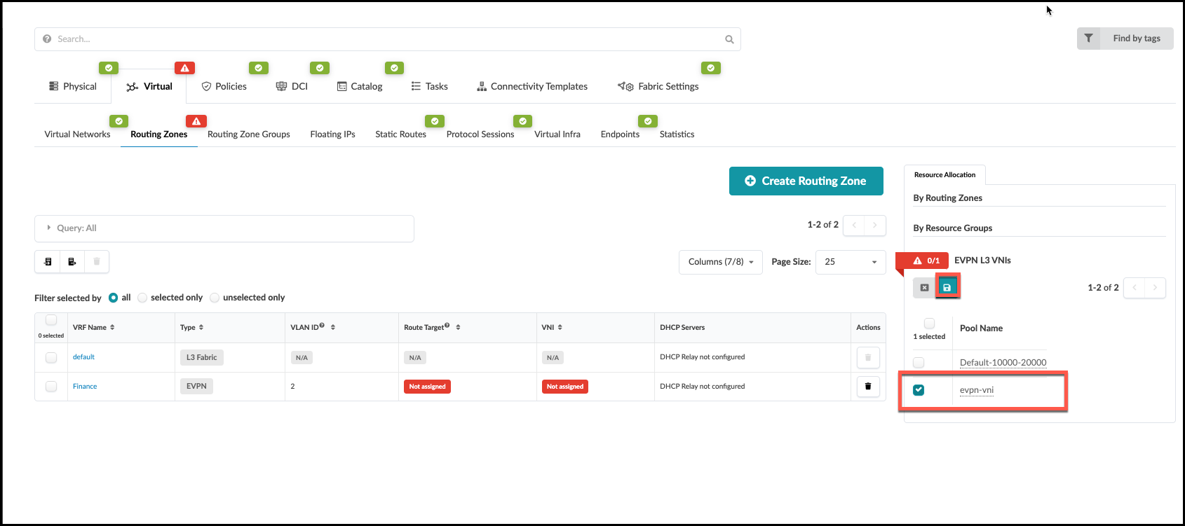 . Click the Save button. The red status indicator turns
green when the resource has been successfully assigned.
+
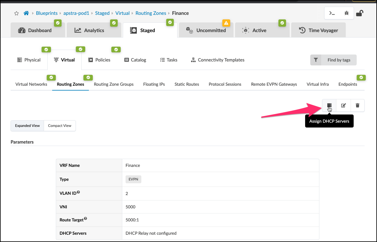
. Select the new Finance RZ in the VRF Name column. In the Finance routing zone detail page, click the Assign DHCP Servers button.
+
. Click the Save button. The red status indicator turns
green when the resource has been successfully assigned.
+
. Select the new Finance RZ in the VRF Name column. In the Finance routing zone detail page, click the Assign DHCP Servers button.
+
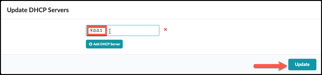
. Enter the DHCP server IP address as shown to 9.0.0.1. Then click
Update.
+
. Click Uncommitted to see the staged changes. It’s informative to look around this tab to become familiar with what results from the input of your Intent.
+
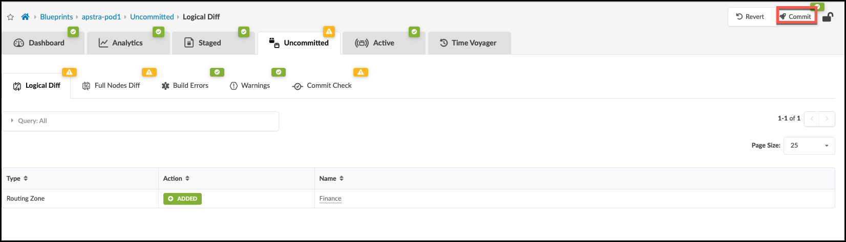
. Click Commit, enter the revision description “Added routing zone”, then click Commit to commit the changes to the Active Blueprint.
Update Connectivity Template for New Routing Zone
We now need to update the Connectivity Template created earlier with the new Routing Zone just created. This allows the Routing Zone to have access to the outside world.
. Navigate to Staged > Connectivity Templates and click
the edit button to the right of the
external_router_ct that we created earlier.
+
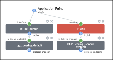
 . Select the Primitives tab then
click IP LInk to add a new primitive to the template.
Then click BGP Peering (Generic System) to add itnto
the template. You should now see two groups of parameters each
representing vrf peering with the external router.
+
. Select the Primitives tab then
click IP LInk to add a new primitive to the template.
Then click BGP Peering (Generic System) to add itnto
the template. You should now see two groups of parameters each
representing vrf peering with the external router.
+
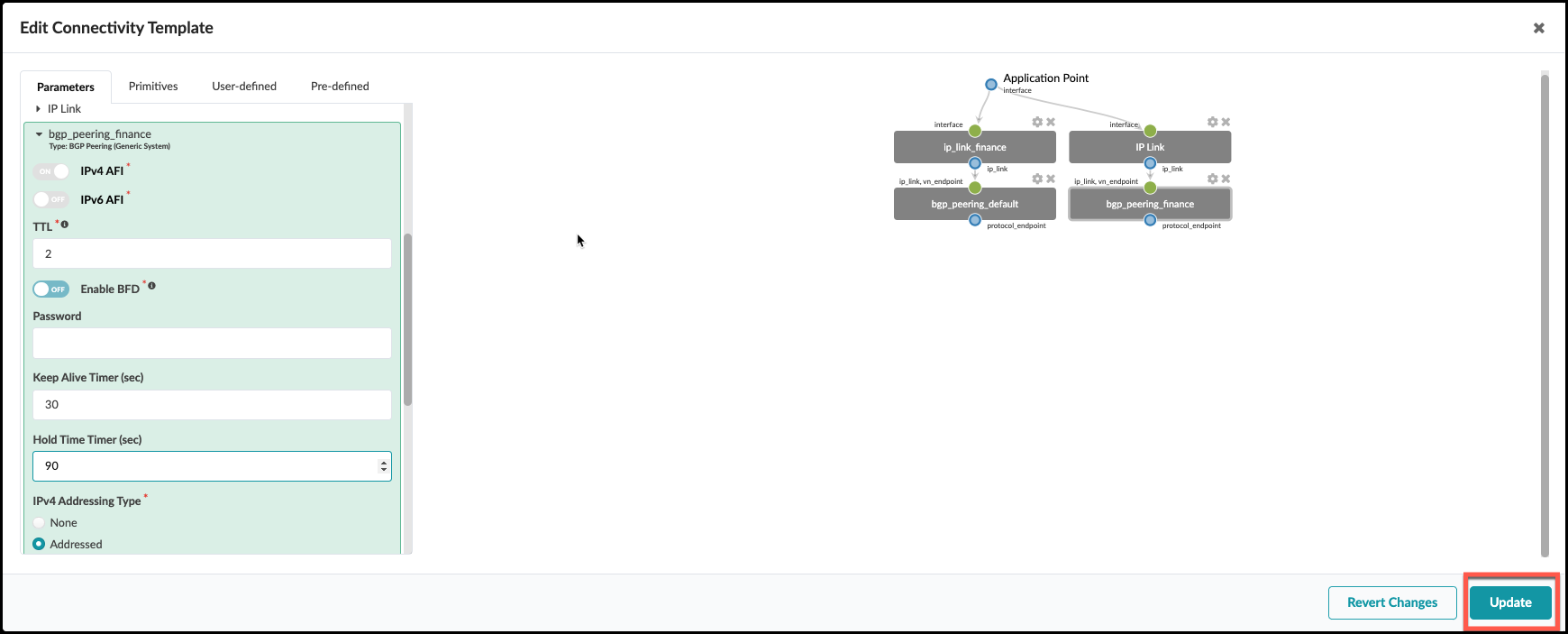
 . Select the Parameters tab and add the following
configuration to the newly added primitives.
+
.Table Update Connectivity Template
[cols##”,”,options##”header”,stripes##hover]
[width##75%]
|####
|Property |Value
|IP Link (edit title) |ip_link_finance
|Interface Type |Tagged
|Routing Zone |Finance
|VLAN ID |2
|BGP Peering (edit title) |bgp_peering_finance
|Keep Alive Timer (sec) |30
|Hold Time Timer (sec) |90
|####
. Click Update.
+
. Select the Parameters tab and add the following
configuration to the newly added primitives.
+
.Table Update Connectivity Template
[cols##”,”,options##”header”,stripes##hover]
[width##75%]
|####
|Property |Value
|IP Link (edit title) |ip_link_finance
|Interface Type |Tagged
|Routing Zone |Finance
|VLAN ID |2
|BGP Peering (edit title) |bgp_peering_finance
|Keep Alive Timer (sec) |30
|Hold Time Timer (sec) |90
|####
. Click Update.
+
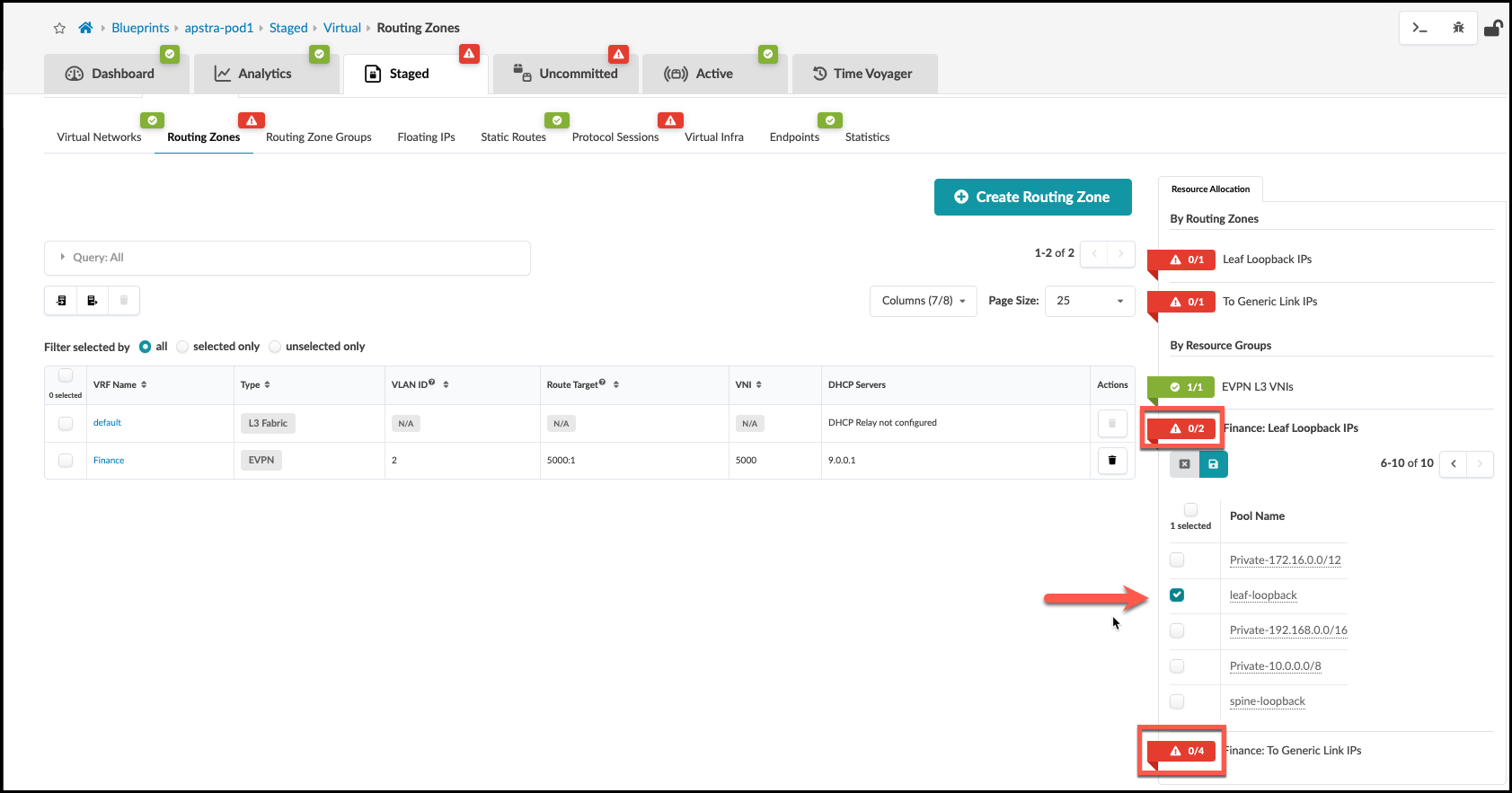
. New resource requirements are needed for the new IP link that’s been added to the CT. Finance: To Generic Link. IPs and *Finance: To Generic Link IPs in Staged > Virtual > Routing Zones > Resource Allocation.
.Table Update Connectivity Template
[cols##”,”,options##”header”,stripes##hover]
[width##75%]
|####
|Property |Value
|Finance: Leaf Loopback IPs |leaf-loopback
|Finance: To Generic Link IPs |external-router
|####
Create Virtual Network: finance-www
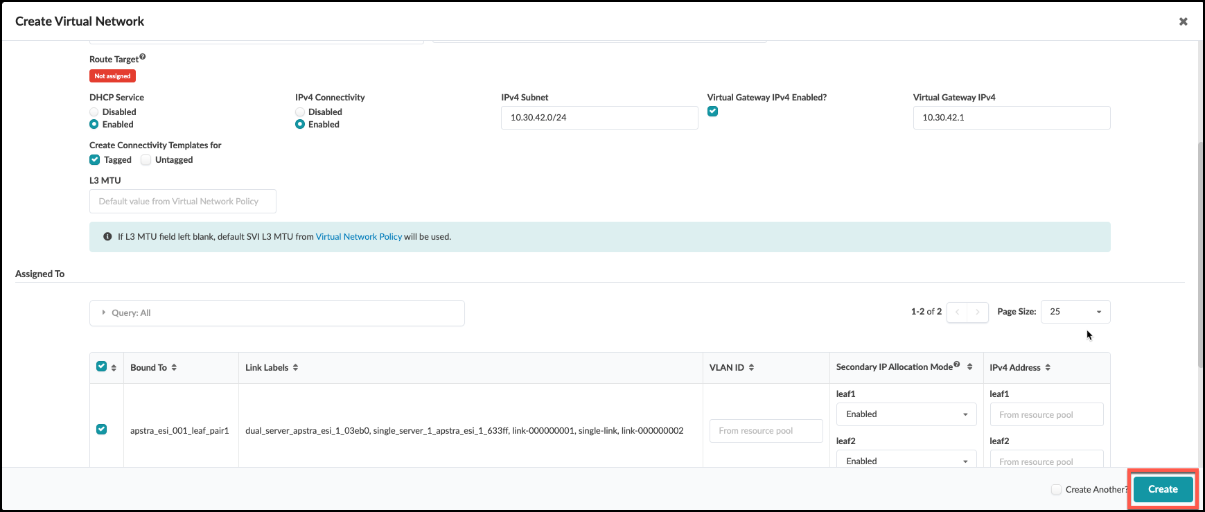
. From the blueprint, navigate to Staged > Virtual > Virtual Networks and click Create Virtual Network. . Enter/select values as shown in the table below. + .Table finance-www VXLAN Values [cols##”,”,options##”header”,stripes##hover] [width##75%] |#### |Parameters |Value |Type |VXLAN |Name |finance-www |Routing Zone |Finance |VNI(s) |[.emphasis]#leave blank# |DHCP Service |Enabled |IPv4 Connectivity |Enabled |IPv4 Subnet |10.30.42.0/24 |Virtual Gateway IP |10.30.42.1 |Create Connectivity Template for |Tagged |#### + . Scroll down to the Assigned To section and select all switches. Leave the VLAN ID fields blank to allow Apstra to automatically assign the VLAN number for each switch. . Click Create to create the virtual network and return to the list view. The new finance-www virtual network appears in the list. You will see red indicators showing where resources are needed. But we are going to hold-off on assigning a pool until we create two more virtual networks.
Create Virtual Network: finance-app
. Click Create Virtual Network. . Enter/select values as shown in the table below. + .Table finance-app VXLAN Parameters [cols##”,”,options##”header”,stripes##hover] [width##75%] |#### |Parameter |Value |Type |VXLAN |Name |finance-app |Routing Zone |Finance |VNI ID |[.emphasis]#leave blank# |DHCP Service |Enabled |IPv4 Connectivity |Enabled |IPv4 Subnet |10.30.43.0/24 |Virtual Gateway IP |10.30.43.1 |Create Connectivity Template for |Tagged |#### + . Scroll down to the Assigned To section and select all switches. Leave the VLAN ID fields blank to allow Apstra to automatically assign the VLAN number. . Click Create to create the virtual network and return to the list view. Check to see if any resources are needed?
Create Inter-rack VXLAN (finance-db)
. Click Create Virtual Networks.
. Enter/select values as shown in the table below.
+
.Table finance-db VXLAN Values
[cols##”,”,options##”header”,stripes##hover]
[width##75%]
|####
|Parameters |Value
|Type |VXLAN
|Name |finance-db
|Routing Zone |Finance
|VNI ID |[.emphasis]#leave blank#
|DHCP Service |Enabled
|IPv4 Connectivity |Enabled
|IPv4 Subnet |10.30.44.0/24
|Virtual Gateway IP |10.30.44.1
|Create Connectivity Template for |Tagged
|####
+
. Scroll down to the Assigned To section and select all
switches. Leave the VLAN ID fields blank to allow Apstra to
automatically assign the VLAN number.
. Click Create to create the virtual network and return
to the list view. The new finance-db virtual network
appears in the list view.
+
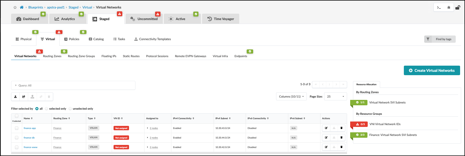
Assign Resources to Virtual Networks
. Click the red status indicator next to the required resources,
then click the Update assignments button to see
available resource pools.
. Select the pool specified in the table below for the required
resource assignments. This will populate the values needed by all three overlays.
+
.Table Resources to Virtual Networks
[cols##”,”,options##”header”,stripes##hover]
[width##75%]
|####
|Resource Requirement |Resource Pool
|VNI Virtual Network IDs |evpn-vni
|####
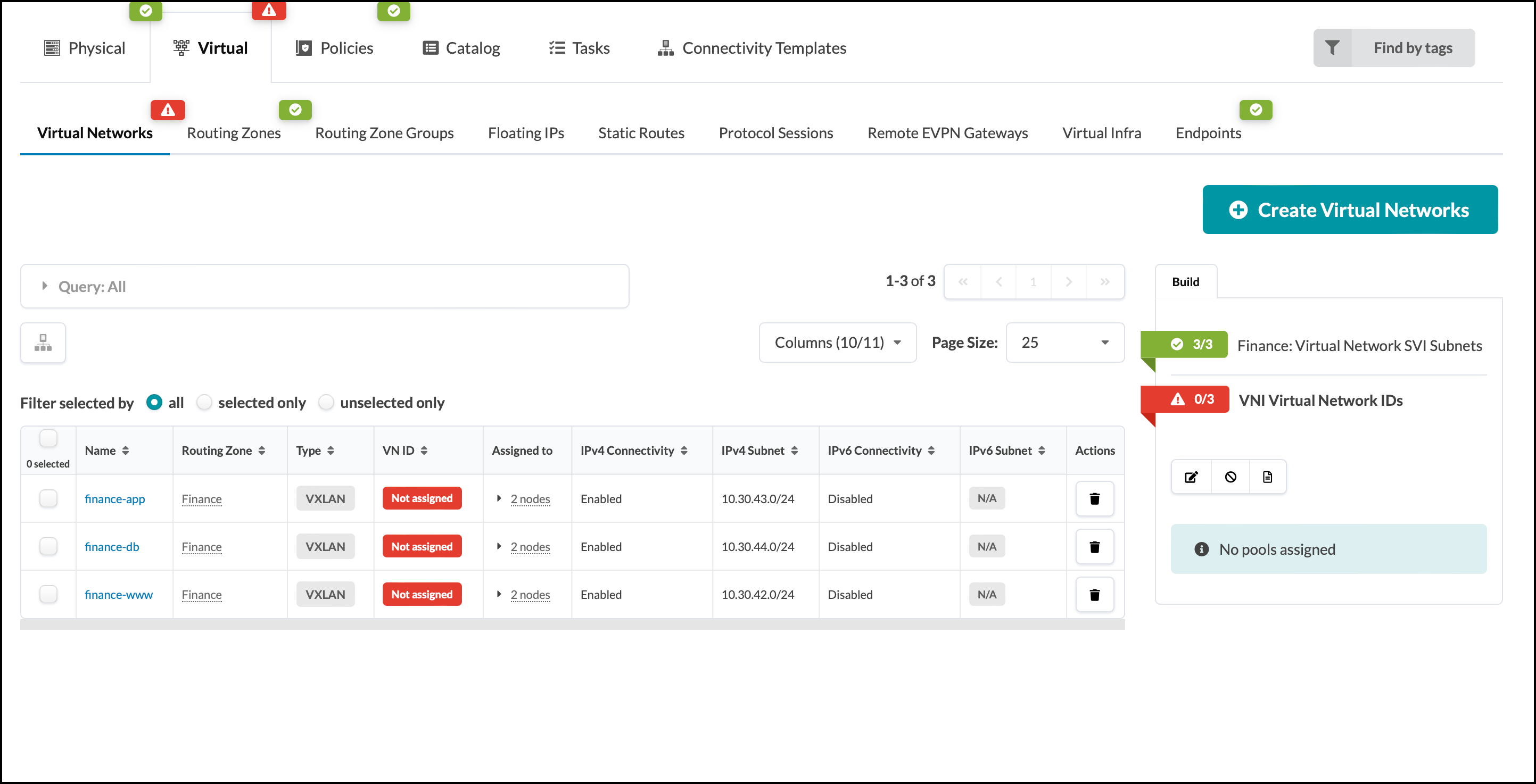
+
. Click the Save button. When the resource has been
successfully assigned, the red status indicator turns green.
+
Assign Virtual Networks to Server Interfaces
. When creating the virtual networks we chose the option to
automatically create a tagged connectivity template in the process.
Interfaces must now be assigned to these connectivity templates for use.
Navigate to Staged > Connectivity Templates and you
will see three new connectivity templates.
+
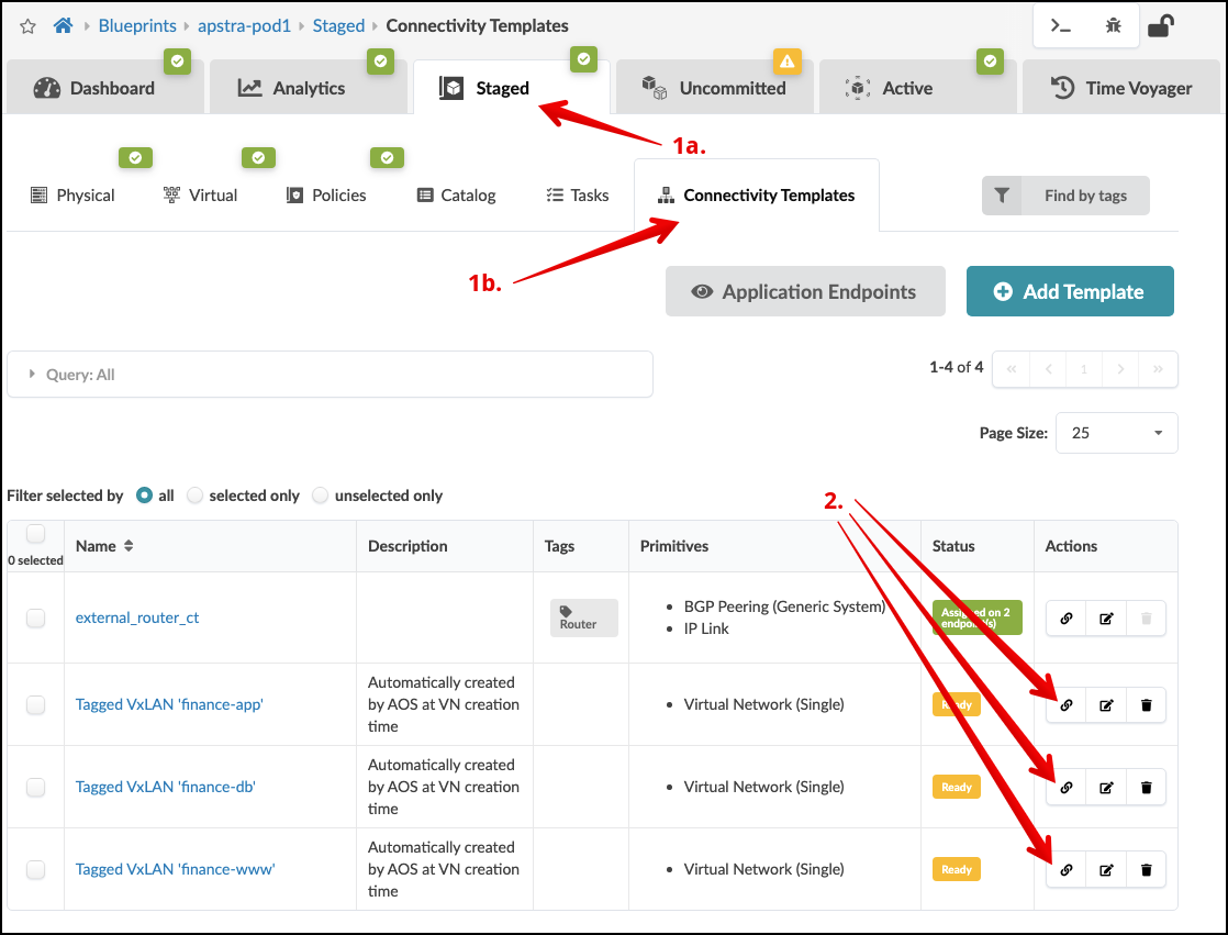 . Select the Assign icon for the Tagged
VxLAN ‘finance-app’ connectivity template. Check the select box to
the right of all interfaces not greyed out. Since this is for server
assignment leave the interfaces tagged with “Router”
unchecked.
+
. Select the Assign icon for the Tagged
VxLAN ‘finance-app’ connectivity template. Check the select box to
the right of all interfaces not greyed out. Since this is for server
assignment leave the interfaces tagged with “Router”
unchecked.
+
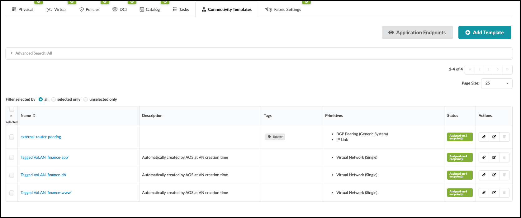
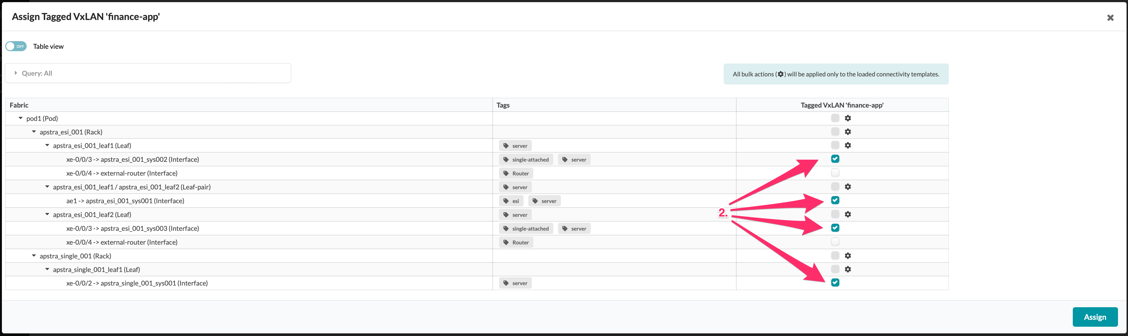 . Click the Assign button and repeat these steps for
the other two connectivity templates. Our Assignment table should look this way.
+
. Click the Assign button and repeat these steps for
the other two connectivity templates. Our Assignment table should look this way.
+
Deploy VXLANs
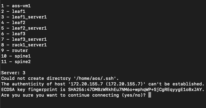
. Click Uncommitted to see the new virtual networks listed in the Logical Diff tab. +  . Enter 3 to connect to leaf1_server1.
If you are asked if you want to continue connecting, enter
yes.
+
. Enter 3 to connect to leaf1_server1.
If you are asked if you want to continue connecting, enter
yes.
+
 . Enter the password for leaf1_server1 (admin).
. run
. Enter the password for leaf1_server1 (admin).
. run sudo dhclient -r && sudo dhclient. This process takes a moment
for interfaces to obtain an IP address.
. Make sure eth1.3 received an address via DHCP after rebooting with the
command: ip -4 -o addr show eth1.3.
. Repeat the dhclient reboot process for the remaining servers if they
have not obtained an IP address already on interface eth1.3.
. Ping the other servers to confirm that you receive responses. For
example: To connect to leaf2_server1, ping 172.20.yoursubnet#.8. (To
stop pinging press ctl-c.)
Check Inter-network Connectivity
Ping the other networks. .
ping -I eth1.3 10.30.42.1.ping -I eth1.3 10.30.43.1.ping -I eth1.3 10.30.44.1
If you are receiving ping responses from all networks, you have reached Milestone 3.
Configlets
Configlets are small configuration segments that are used to apply device settings that fall outside the Apstra Reference Design parameters. Examples of common Configlet usage are items like syslog, SNMP, TACACS/RADIUS, management interface ACLs, control plane policing and NTP settings. The NTP example is the one we will use to show you the process of working with Configlets.
In addition, we are going to use another mechanism called Property Sets. These increase flexibility by allowing us to use variables in a Configlet. This is quite handy if we would like to use a common Configlet structure for our devices, but not all devices require the same values. This exercise calls for us to add the Junos style and variables to an existing NTP Configlet. Property Sets will supply the IP address for the server and identify the VRF to apply the configurations into.
Always remember that Configlets are a powerful way to apply configuration that falls outside of the Apstra Reference Designs. In other words, do not use Configlets for features that Apstra manages, itself. Doing so can interfere with the proper operation of the solution. It is critical that the configurations applied in Configlets are thoroughly verified before applying them in a Blueprint. Otherwise, malformed Configlets will cause errors and interfere with deployment.
Edit NTP Configlet
Our exercise calls for us to edit a Configlet and add an additional Config Style for Junos.
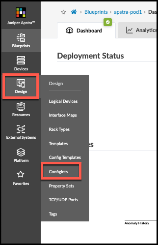
. Navigate to Design > Configlets, where the global Configlets reside.
+
 +
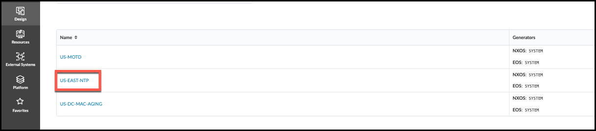
. Click the US-EAST-NTP that is already present and view its details.
+
+
. Click the US-EAST-NTP that is already present and view its details.
+
. Click the Edit button (top-right), then at the bottom
of the dialog, click Add a Style.
+
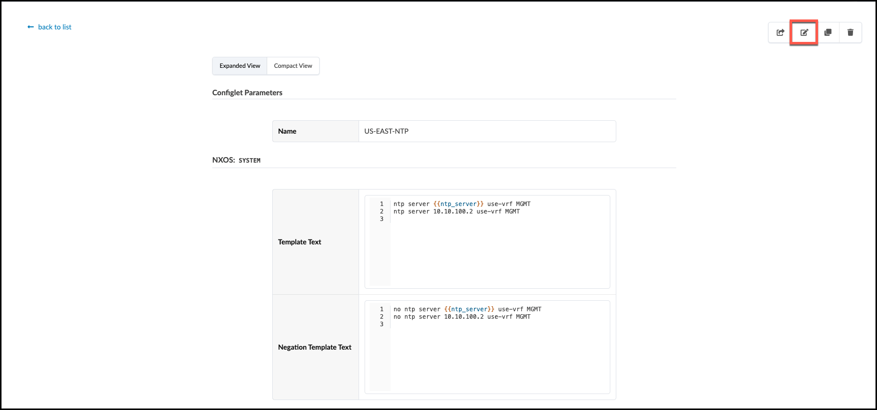
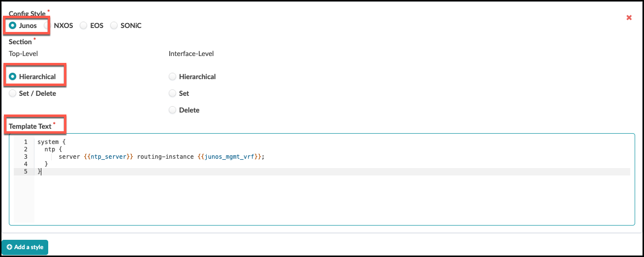
. In the Edit Configlet view, set Config Style to Junos. Under Top-level, select Hierarchical. Copy-and-paste the Template Text below the image into the Configlet, as shown. Be sure to be accurate in this step, so we don’t get errors later. Once complete, press the Update button in the lower right to save your work.
+
 +
Template Text
[source,jinja]
+
Template Text
[source,jinja]
system { ntp { server {{ntp_server}} routing-instance {{junos_mgmt_vrf}}; } }
Import the Configlet and Property Sets
The Configlet we edited resides in the global Design area of the Apstra server. To use it, we need to import the NTP Configlet into a Blueprint where it can be applied to our Junos devices. We also need to bring in two Property Sets containing values for the variables. To do this, we go into the Blueprint and move to the Catalog area.
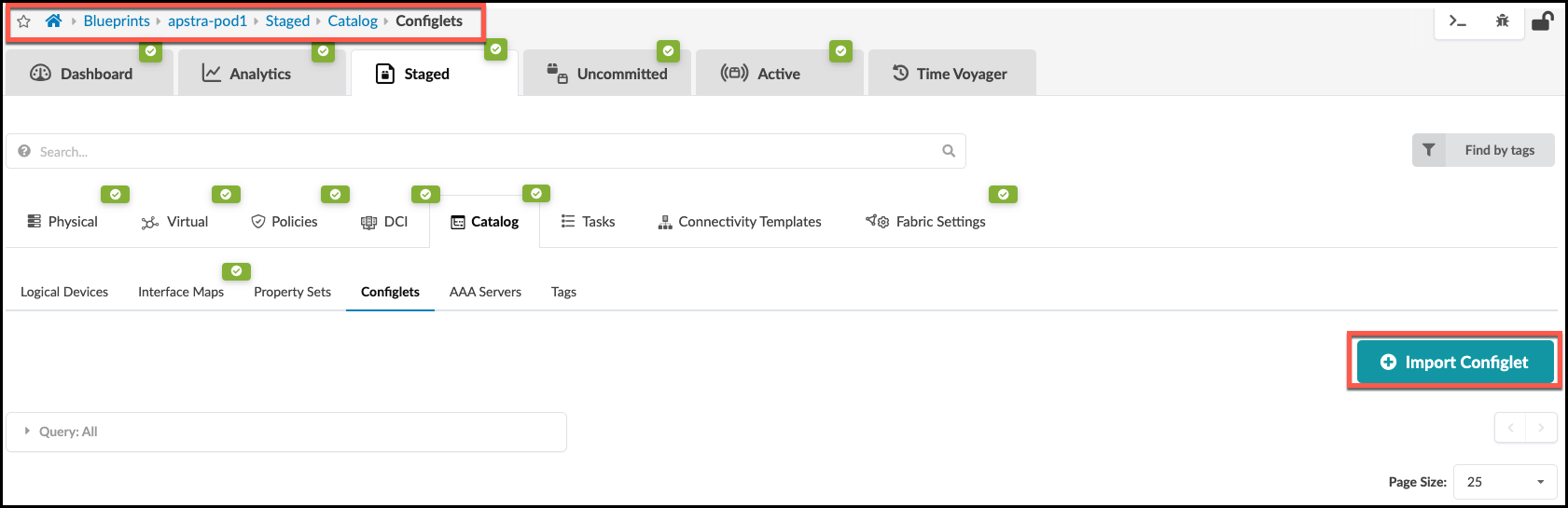
. Navigate to the Staged > Catalog > Configlets area and click Import Configlet.
+
 +
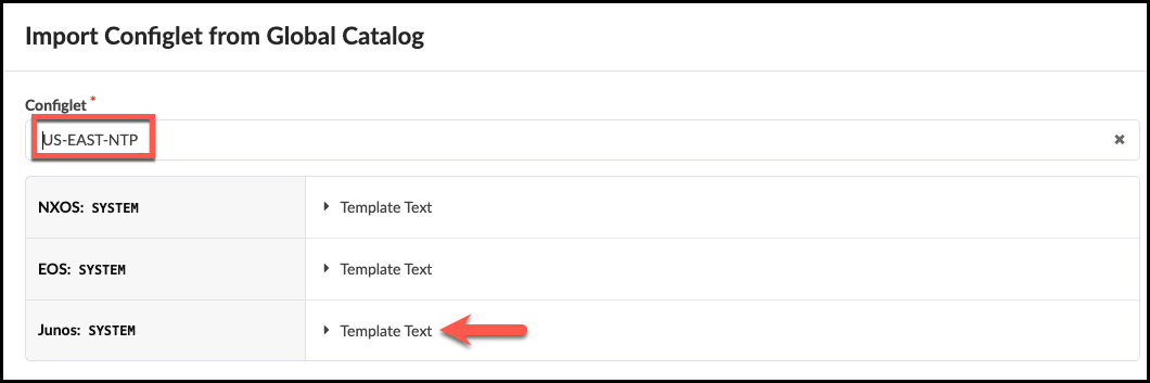
. In the dialog box, select US-EAST-NTP that we edited just earlier. You can see from this view that this Configlet has the Junos template text that it did not have, previously.
+
+
. In the dialog box, select US-EAST-NTP that we edited just earlier. You can see from this view that this Configlet has the Junos template text that it did not have, previously.
+
 +
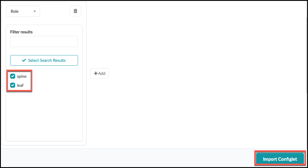
. Now, scroll down a bit to specify the device roles to which this Configlet will be applied. Select spine and leaf. Click Import Configlet.
+
+
. Now, scroll down a bit to specify the device roles to which this Configlet will be applied. Select spine and leaf. Click Import Configlet.
+
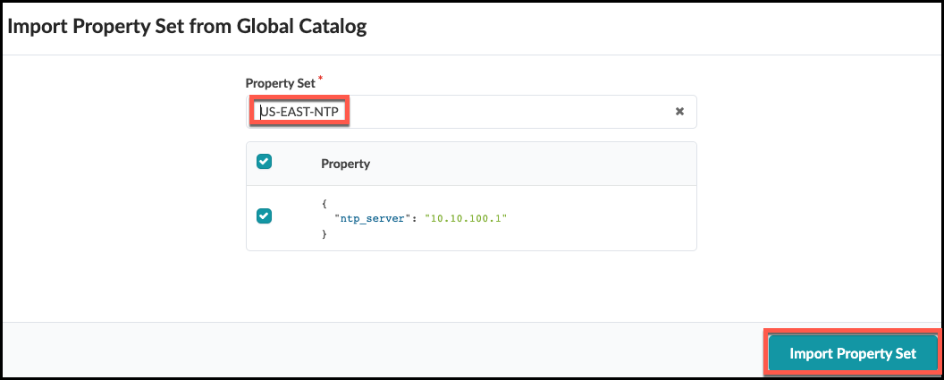
. The Blueprint must also contain the Property Sets that align with the Configlet’s variables. This Configlet expects two values to be supplied in this manner. There are two existing Property Sets in the global Design > Property Sets area that we need. Each one of these contains values we need. One is for the NTP server IP address and the other is for the VRF values. Navigate inside the Blueprint to Staged > Catalog > Property Sets and click Import Property Set.
. Select US-EAST-NTP from the drop-down list, then
click Import Property Set. This copies the Property Set into the Blueprint catalog.
+
 . Repeat these same steps for the second property set, MGMT VRF.
. Great job! Now we can review our work and commit it to the Blueprint. Select the Uncommitted tab at the top center. It presently has a yellow icon.
Note the items present in the list.
+
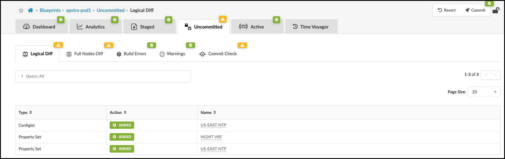
. Click Commit. Enter the revision description “Added Junos to US-EAST-NTP configlet.”, then click Commit again to commit for the changes to be added to the devices in the Blueprint. If you would like to view the Configlet contents in the device configurations, view the Rendered Configuration for each device.
Intent-Based Analytics - Probe Basics
Instantiate Predefined IBA Probe
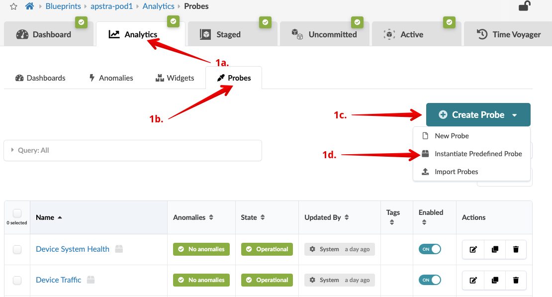
. From the blueprint, navigate to Analytics > Probes,
click Create Probe and select
Instantiate Predefined Probe.
+
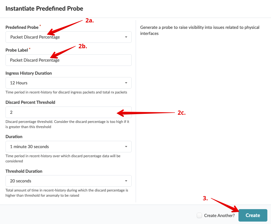
 . Enter/select values as shown in the table below. Leave other values as
they are.
+
.Table Packet Discard Percentage Probe
[cols##”,”,options##”header”,stripes##hover]
[width##75%]
|####
|Parameter |Value
|Predefined Probe |Packet discard percentage
|Probe Label |Packet discard percentage
|Discard Percent Threshold |2
|####
+
. Click Create to create the probe and go to the
Packet discard percentage details view.
+
. Enter/select values as shown in the table below. Leave other values as
they are.
+
.Table Packet Discard Percentage Probe
[cols##”,”,options##”header”,stripes##hover]
[width##75%]
|####
|Parameter |Value
|Predefined Probe |Packet discard percentage
|Probe Label |Packet discard percentage
|Discard Percent Threshold |2
|####
+
. Click Create to create the probe and go to the
Packet discard percentage details view.
+
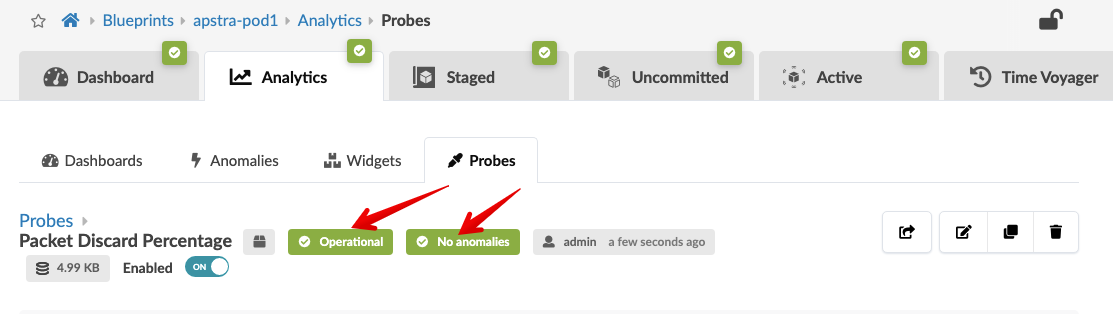
 . Watch for the two green labels to appear that confirm that the status
of the probe is operational and that no anomalies exist.
+
. Watch for the two green labels to appear that confirm that the status
of the probe is operational and that no anomalies exist.
+
Stopping and Starting IBA Probe
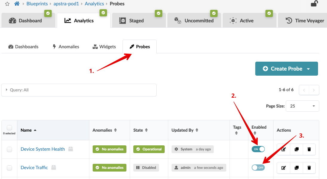
. Click the Probes tab to return to the list view.
. To stop an enabled probe, click the Enabled toggle
off.
. To start a disabled probe, click the Enabled toggle
on.
+
Root Cause Identification
The root cause identification system automatically correlates anomalies to identify the actual cause of connectivity problems. This eliminates unnecessary work and troubleshooting for an operator.
Enabling Connectivity RCI Fault Model
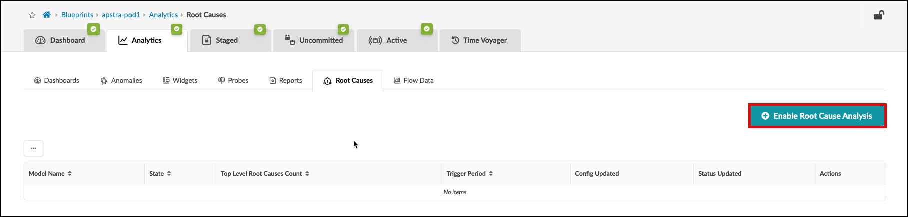
. From the blueprint, navigate to Analytics > Root Causes
and click Enable Root Cause Analysis. You can set the trigger period to any value, if you wish. This will enable the RCI probe.
+
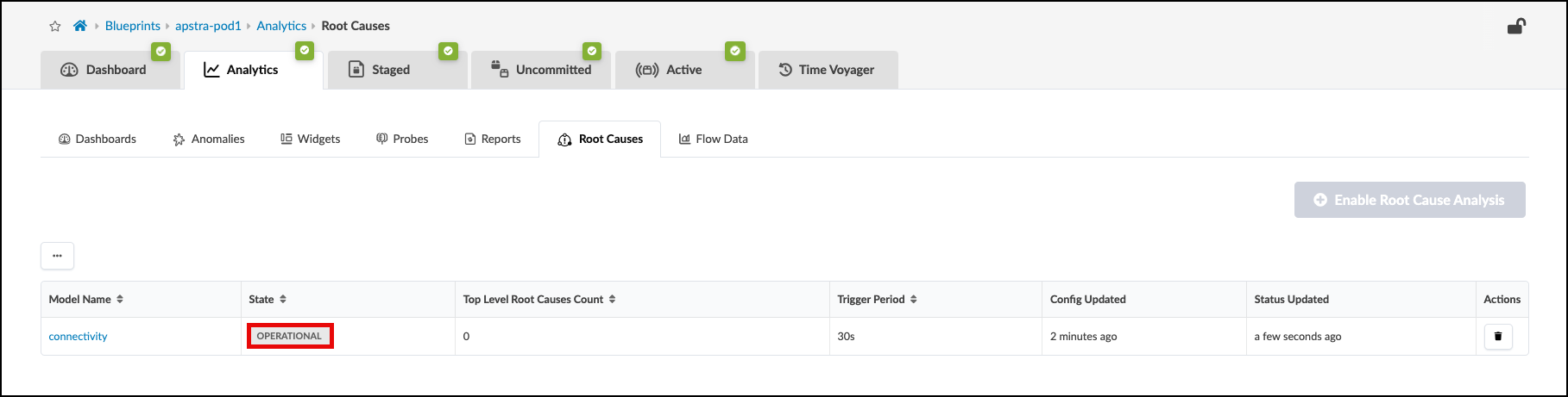
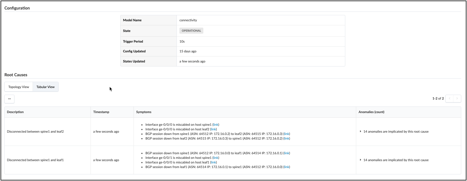
 . Notice that the connectivity model is now in the operational state.
+
. Notice that the connectivity model is now in the operational state.
+
With Root Cause Identification enabled, link or interface failures will be identified with precision. RCI can be tested in this lab pod by misconfiguring fabric links.
. Navigate to the Staged > Physical > Links and choose the Edit tool.
+

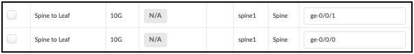
. Locate the Spine-to-Leaf links for Spine1 in the table, as shown.
+
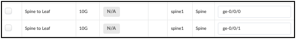
. Swap the designated interfaces to the values shown in this table.
+
 . Navigate to the Uncommitted tab and review the staged changes, then commit them to the Blueprint. Swapping the interface settings will disrupt BGPs peering between fabric devices. This will cause multiple anomaly reports, all of which will be correllated by the Root Cause probe. The view below shows the result of the analysis. Explore all the areas of this view to see the details of the Root Cause diagnosis.
+
. Navigate to the Uncommitted tab and review the staged changes, then commit them to the Blueprint. Swapping the interface settings will disrupt BGPs peering between fabric devices. This will cause multiple anomaly reports, all of which will be correllated by the Root Cause probe. The view below shows the result of the analysis. Explore all the areas of this view to see the details of the Root Cause diagnosis.
+
If you wish to return your fabric links to the intended operational state, there are three ways to do this; you can edit the Links table (also known as the Cable Map) again to set the original interface assignments. Or, you could use fetch discovered LLDP data and allow the tool to reset the intended assignment to match the cabling. The last method is Time Voyager, where you could simply restore the fabric snapshot from just before you committed the interface swap.
Troubleshooting Scenario
Troubleshooting Config Deviation
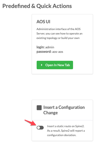
. Let’s simulate a config change on one of the devices.
. Go to the CloudLabs portal, and toggle on Insert a
Configuration Change.
+
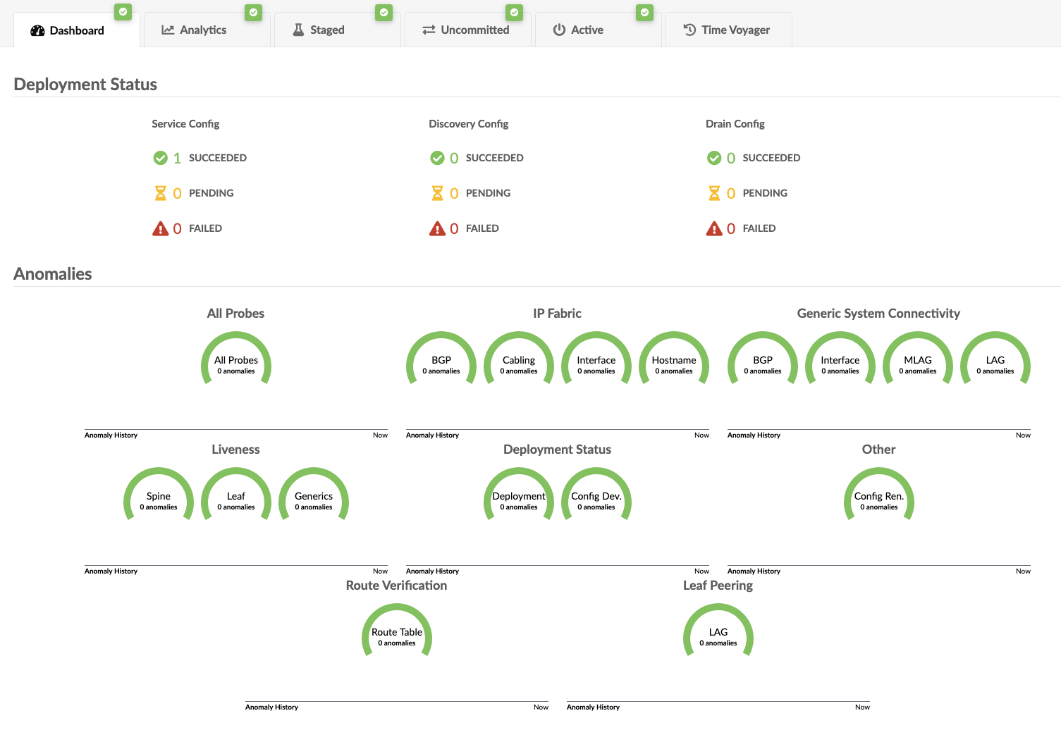
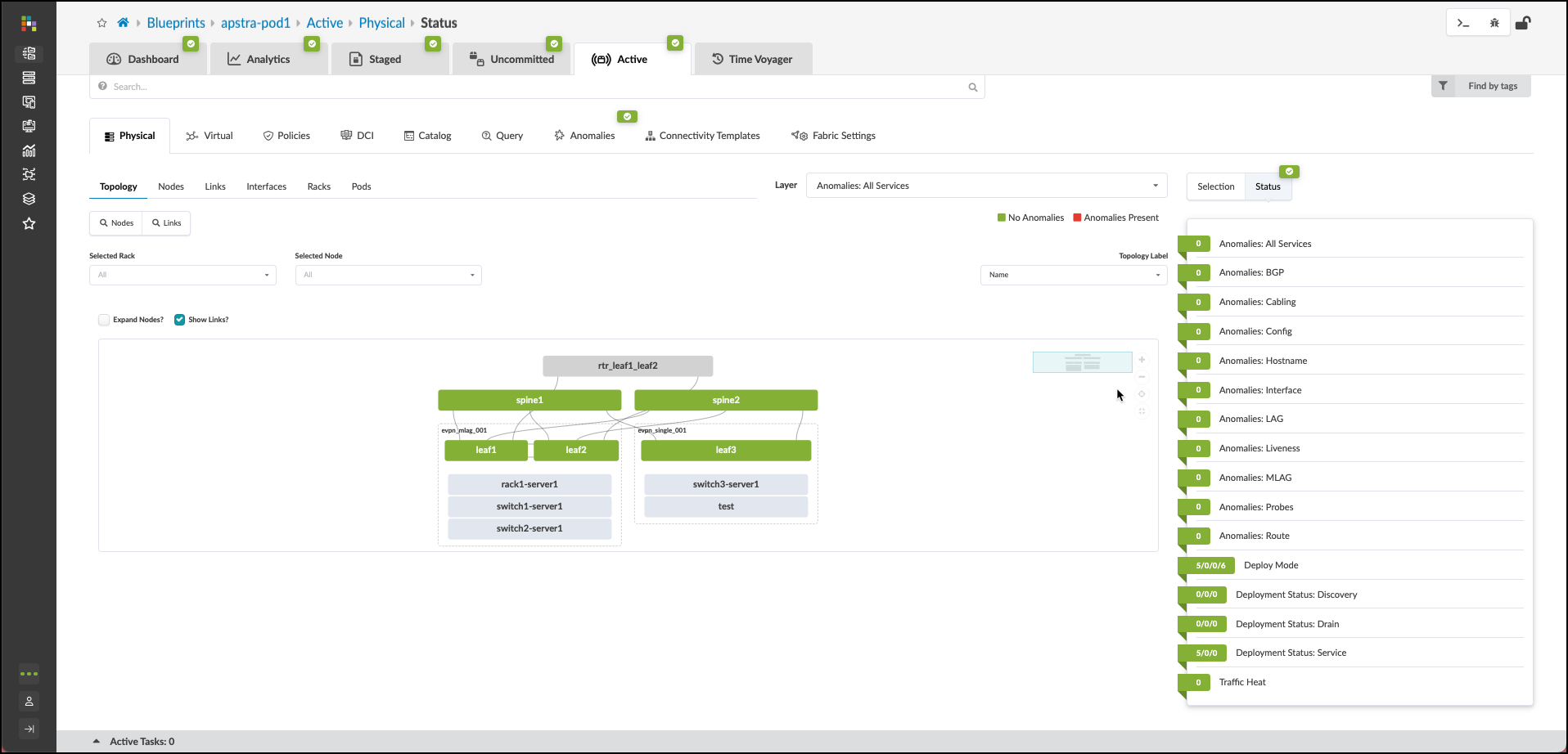
 . Return to the dashboard. In about a minute, an anomaly appears in the
Deployment Status section of the dashboard.
. Click the anomaly to go to the Anomalies view.
+
. Return to the dashboard. In about a minute, an anomaly appears in the
Deployment Status section of the dashboard.
. Click the anomaly to go to the Anomalies view.
+
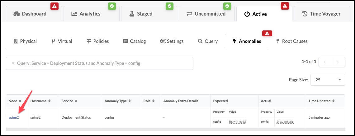 . Click spine2 to go to the telemetry view for spine2.
Any anomalies are listed.
+
. Click spine2 to go to the telemetry view for spine2.
Any anomalies are listed.
+
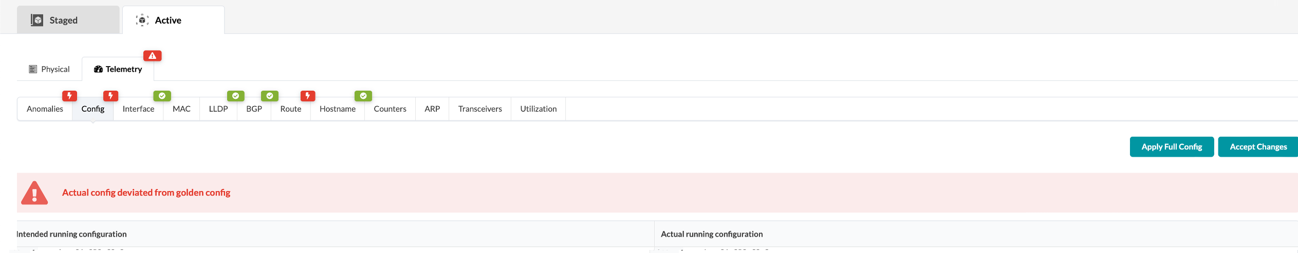
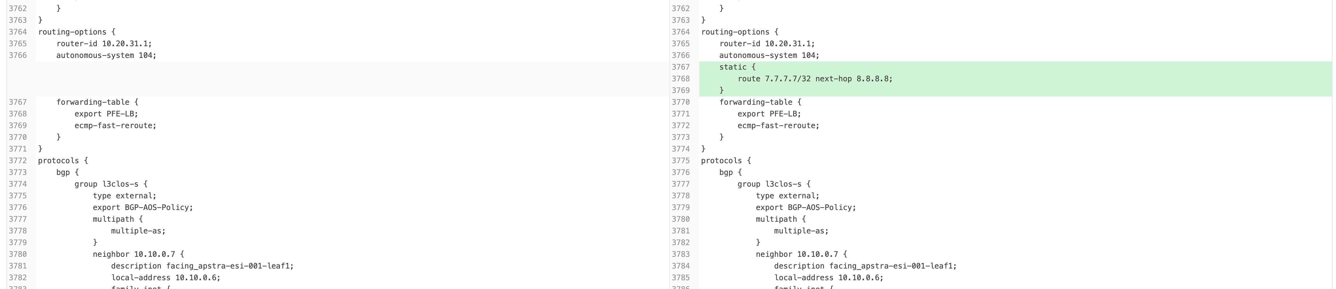
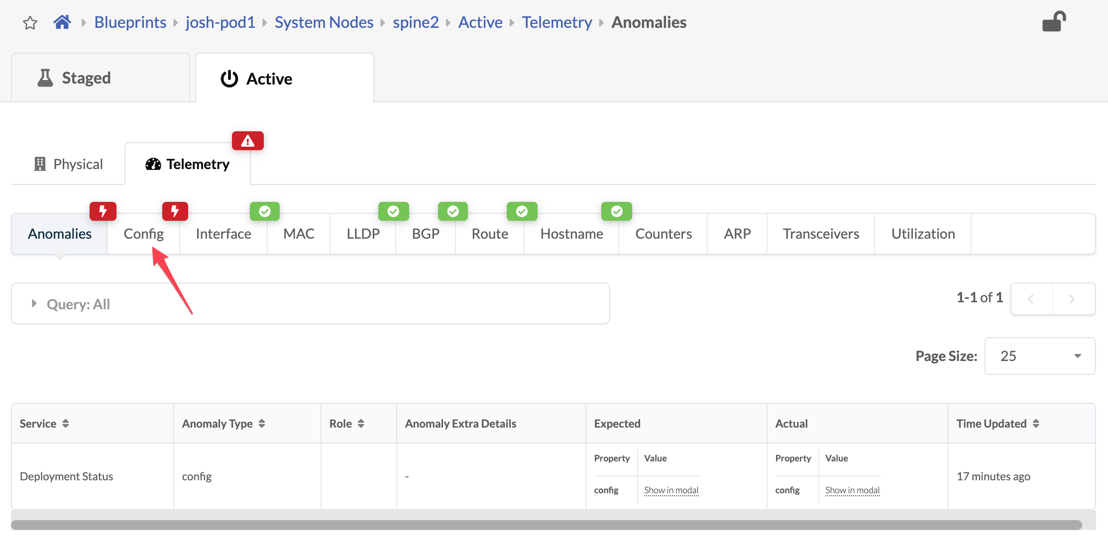 . Click the Config tab to see details about the anomaly. Scroll down to
see the deviation.
+
. Click the Config tab to see details about the anomaly. Scroll down to
see the deviation.
+
 +
+
After you’ve identified the problem, you can restore the original config by returning to the CloudLabs portal and toggling off Insert a Configuration Change. You can also click Apply Full Config in the Apstra UI to revert the device to the golden configuration
.Milestone 4
When you have identified the problems in the network you have completed the lab.
Congratulations!
Conclusion and Next Steps
In this lab, you have performed the exercises related to all items in the list below:
[width##75%] |#### |- Device Management |- Resource Management |- Blueprint Deployment |- Multitenancy and Virtual Overlay Networks |- Configlets and Extending the DC Reference Architecture |- Intent-based Analytics |- Enable RCI |- Configuration Anomaly and Resolution |####
Please take a look at the network you have built and the services you have enabled. Contrast the experience with how it would have been performing all the tasks manually.
We wish to thank you for your time and interest in the Apstra solution. After completing the lab exercises, you have still only experienced a portion of its capabilities. Please locate the additional lab scenarios and consider performing those listed. You will then possess a more complete perspective on the power and flexibility that Apstra provides.
This concludes Lab Guide 1 - Juniper.
Milestone 1
Juniper/Apstra Product SE Team v4.2.2 2024 :doctype: book //:sectnums: :appversion: 0.2 :language: asciidoc
You have reached the first milestone towards the completion of your lab.

You have completed these lab exercises:
. Defined Resource Pools. . Designed your Rack Types. . Assembled your Template. . Acknowledged your virtual Junos devices.
Milestone 2
Juniper/Apstra Product SE Team v4.2.2 2024 :doctype: book //:sectnums: :appversion: 0.2 :language: asciidoc
You have reached the first milestone towards the completion of your lab.

You have now completed these additional exercises:
. Deployed the Blueprint . Assigned Resources . Connected the fabric to the external router
Milestone 3
Juniper/Apstra Product SE Team v4.2.2 2024 :doctype: book //:sectnums: :appversion: 0.2 :language: asciidoc
You have reached the first milestone towards the completion of your lab.

You have now completed these exercises:
. Defined Routing Zones . Created three fabric overlay networks . Assigned the networks to the virtual servers . Deployed and tested the intended architecture.
Milestone 4
Juniper/Apstra Product SE Team v4.2.2 2024 :doctype: book //:sectnums: :appversion: 0.2 :language: asciidoc
You have reached the first milestone towards the completion of your lab.
!(./image/4_2/milestone-4.png)
You have completed these exercises:
. Created and applied a Configlet . Enabled IBA probes. . Resolved a Configuration Deviation . Caused and observed a Root Cause Identificaton