EVPN Multihoming Lab
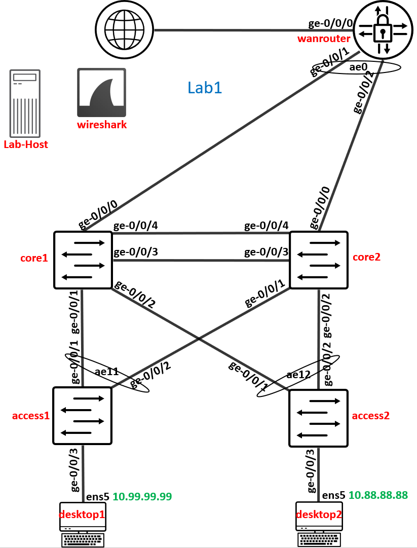
In this Lab we will use the left side of the Lab Topology to setup EVPN Multihoming.
Create Switch Template
Warning
Do NEVER configure a network locally at a Switch. This is a door to chaos! Always configure a Network via Switch Template and then import into the Fabric!
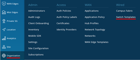
Go to Organization -> Switch Templates
EMBEDDED BELOW: You will find a JSON File creating the Switch Template if you are in a hurry.

{
  "additional_config_cmds": [],
  "networks": {
    "vlan1099": {
      "vlan_id": "1099",
      "subnet": "10.99.99.0/24"
    },
    "vlan1088": {
      "vlan_id": "1088",
      "subnet": "10.88.88.0/24"
    },
    "vlan1033": {
      "vlan_id": "1033",
      "subnet": "10.33.33.0/24"
    }
  },
  "port_usages": {
    "vlan1099": {
      "mode": "access",
      "disabled": false,
      "port_network": "vlan1099",
      "voip_network": null,
      "stp_edge": false,
      "mac_auth_protocol": null,
      "all_networks": false,
      "networks": null,
      "port_auth": null,
      "allow_multiple_supplicants": null,
      "enable_mac_auth": null,
      "mac_auth_only": null,
      "guest_network": null,
      "bypass_auth_when_server_down": null,
      "dynamic_vlan_networks": null,
      "speed": "auto",
      "duplex": "auto",
      "mac_limit": 0,
      "persist_mac": false,
      "poe_disabled": false,
      "enable_qos": false,
      "storm_control": {},
      "mtu": 9014,
      "description": "",
      "disable_autoneg": false
    },
    "vlan1088": {
      "mode": "access",
      "disabled": false,
      "port_network": "vlan1088",
      "voip_network": null,
      "stp_edge": false,
      "mac_auth_protocol": null,
      "all_networks": false,
      "networks": null,
      "port_auth": null,
      "allow_multiple_supplicants": null,
      "enable_mac_auth": null,
      "mac_auth_only": null,
      "guest_network": null,
      "bypass_auth_when_server_down": null,
      "dynamic_vlan_networks": null,
      "speed": "auto",
      "duplex": "auto",
      "mac_limit": 0,
      "persist_mac": false,
      "poe_disabled": false,
      "enable_qos": false,
      "storm_control": {},
      "mtu": 9014,
      "description": "",
      "disable_autoneg": false
    },
    "vlan1033": {
      "mode": "access",
      "disabled": false,
      "port_network": "vlan1033",
      "voip_network": null,
      "stp_edge": false,
      "mac_auth_protocol": null,
      "all_networks": false,
      "networks": null,
      "port_auth": null,
      "allow_multiple_supplicants": null,
      "enable_mac_auth": null,
      "mac_auth_only": null,
      "guest_network": null,
      "bypass_auth_when_server_down": null,
      "dynamic_vlan_networks": null,
      "speed": "auto",
      "duplex": "auto",
      "mac_limit": 0,
      "persist_mac": false,
      "poe_disabled": false,
      "enable_qos": false,
      "storm_control": {},
      "mtu": 9014,
      "description": "",
      "disable_autoneg": false
    },
    "myuplink": {
      "mode": "trunk",
      "disabled": false,
      "port_network": "default",
      "voip_network": null,
      "stp_edge": false,
      "mac_auth_protocol": null,
      "port_auth": null,
      "all_networks": true,
      "networks": [],
      "speed": "auto",
      "duplex": "auto",
      "mac_limit": 0,
      "persist_mac": false,
      "poe_disabled": false,
      "enable_qos": false,
      "storm_control": {},
      "mtu": 9018,
      "description": "",
      "disable_autoneg": false
    },
    "dynamic": {
      "mode": "dynamic",
      "reset_default_when": "link_down",
      "rules": []
    }
  },
  "no_system_defined_port_usages": false,
  "switch_mgmt": {
    "config_revert_timer": 10,
    "root_password": "",
    "protect_re": {
      "enabled": false
    },
    "tacacs": {
      "enabled": false
    }
  },
  "radius_config": {
    "auth_servers": [],
    "acct_servers": [],
    "auth_servers_timeout": 5,
    "auth_servers_retries": 3,
    "fast_dot1x_timers": false,
    "acct_interim_interval": 0,
    "auth_server_selection": "ordered",
    "coa_enabled": false,
    "coa_port": ""
  },
  "vrf_config": {
    "enabled": false
  },
  "remote_syslog": {
    "enabled": false
  },
  "snmp_config": {
    "enabled": false
  },
  "dhcp_snooping": {
    "enabled": false
  },
  "bgp_config": null,
  "routing_policies": {},
  "dns_servers": [],
  "dns_suffix": [],
  "ntp_servers": [],
  "acl_policies": [],
  "port_mirroring": {},
  "switch_matching": {
    "enable": true,
    "rules": []
  },
  "name": "Topology1"
}
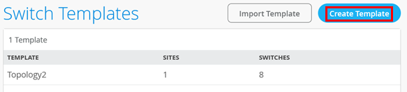
Create a new Template to the existing one calling it “Topology1”.
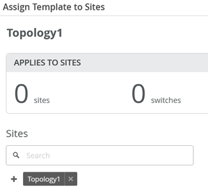
Assign it to
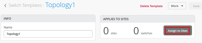
Assign to the Site also called Topology1
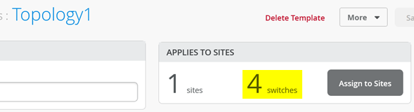
Check you have now 4 Switches applicable to this Template
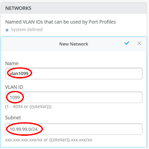
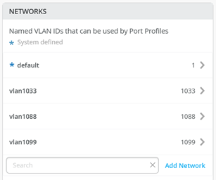
Configure 3 Networks:
First Network
Name=vlan1099
VLAN ID=1099
Subnet=10.99.99.0/24
Second Network
Name=vlan1088
VLAN ID=1088
Subnet=10.88.88.0/24
Third Network
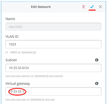
Name=vlan1033
VLAN ID=1033
Subnet=10.33.33.0/24
Below is a screenshot from the first Network
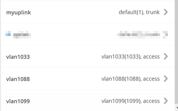
The resulting configuration should look like below
Configure Port Profiles:
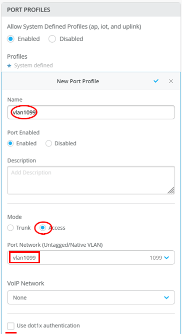
First Port Profile
Name=vlan1099
Mode=Access
Port Network=vlan1099
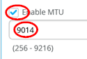
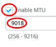
Enable MTU=Checked
MTU value=9014
Second Port Profile
Name=vlan1088
Mode=Access
Port Network=vlan1088
Enable MTU=Checked
MTU value=9014
Third Port Profile
Name=vlan1033
Mode=Access
Port Network=vlan1033
Enable MTU=Checked
MTU value=9014
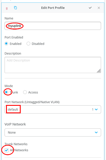
Forth Port Profile
Name=myuplink
Mode=Trunk
Port Network=default
Trunk Networks=All Networks
Enable MTU=Checked
MTU value=9018
.
Here is our own uplink profile
.
The resulting configuration should look like the below
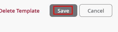
Save your Template
Create EVPN Multihoming Fabric
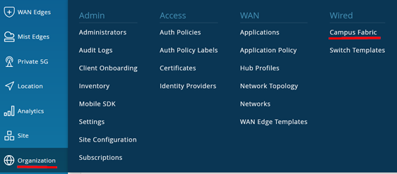
Go to Organization -> Campus Fabric like below indicated.
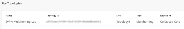
Make sure you are in Site “Toplology1” and create a new Lab
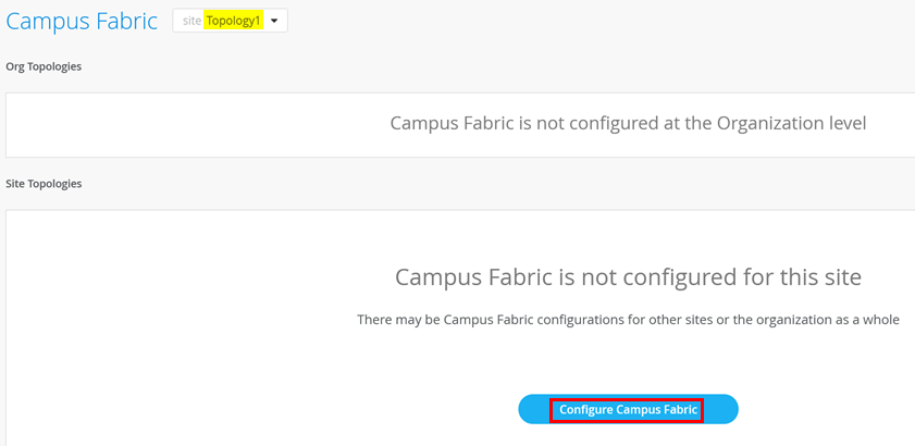
Create new Multihoming Lab but DO NOT CHANGE THE DEFAULTS on this Page

Go to the next Page. Assign the Nodes as shown below

Go to the next Page. Add the three Networks that appear now

The following warning message should appear now.
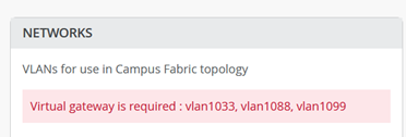
Go into each of the 3 Networks assigning the first host IP as virtual Gateway IP-Address to get rid of the warning message. Example below for VLAN 1033.
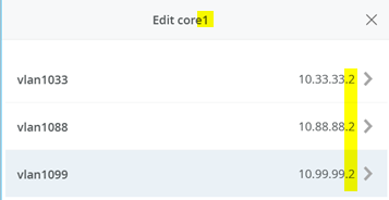
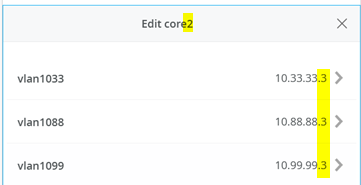
Now check the resulting “Other IP Configuration” made on core1 and core2 for the static VGA addresses auto assigned.
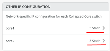
Core1 Switch
Core2 Switch
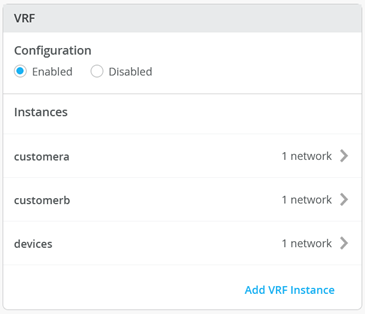
Enable VRF configuration as below

Add the following VRF’s
First VRF
Name=customera
Networks=vlan1099
Extra Routes
Route=0.0.0.0/0
Via=10.99.99.254
Second VRF
Name=customerb
Networks=vlan1088
Extra Routes
Route=0.0.0.0/0
Via=10.88.88.254
Third VRF
Name=devices
Networks=vlan1033
Extra Routes
Route=0.0.0.0/0
Via=10.33.33.254
Example for first VRF below:

The resulting configuration should look like the below
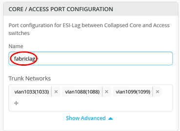
Before you advance the Page add a name like “fabriclag” to the Core / Access Port Configuration like below.
Go now to the next Page where you configure the Links between the systems.
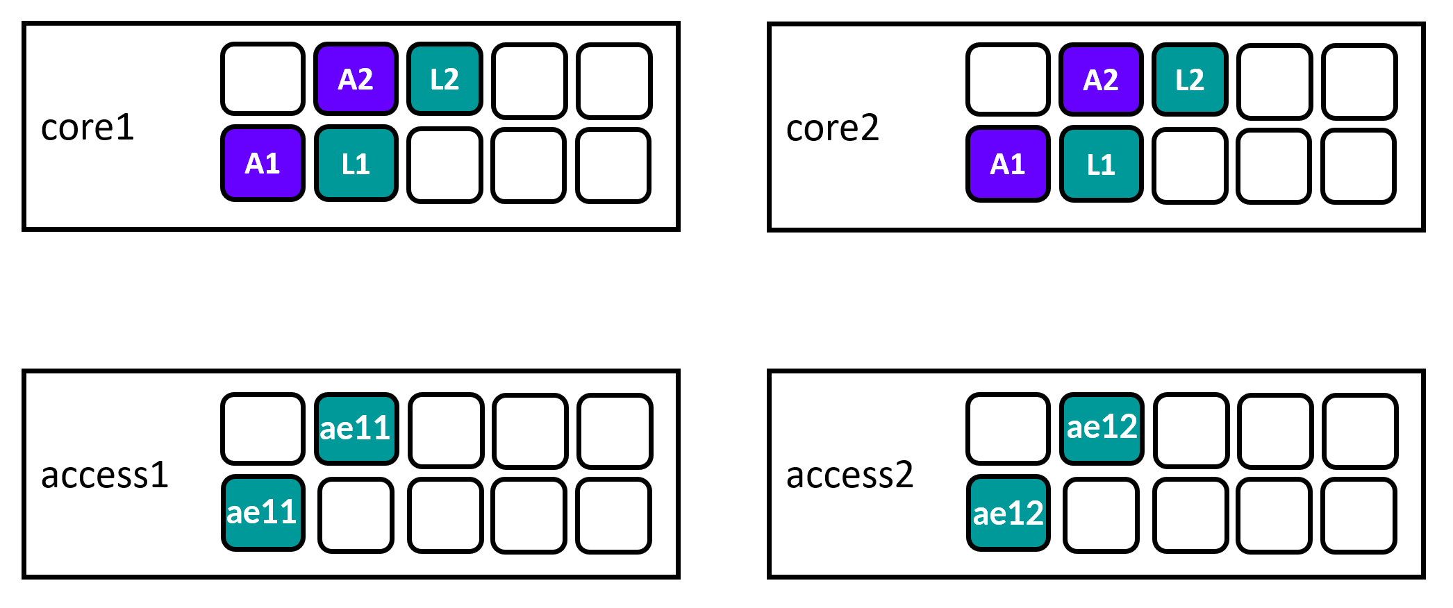
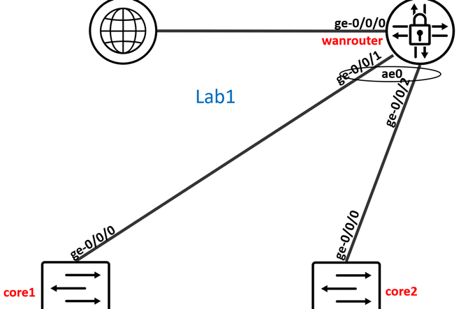
As a reminder these are the Links we do configure in this step.
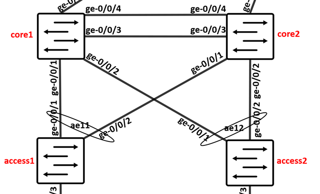
The cheat-sheet below tells you what to click and what the access/link ID is.
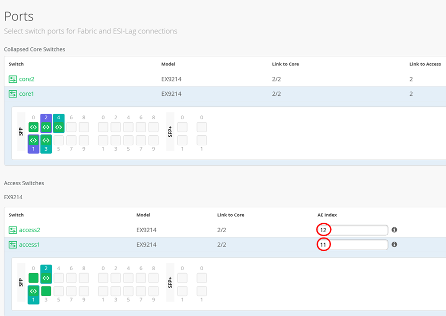
When configuring Access Switch Ports you just need to tell the Link is a “ge-“ Interface.

Warning
Please ensure that the Access Switches do NOT use the AE Index 0 as we use that on the uplink of the WAN-Router.
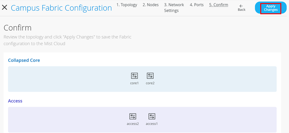
When ready go to next Page and apply the configuration.
.
Go to core1 and core2 switches via remote shell and review bgp and lacp interface status confirming the Fabric came up.
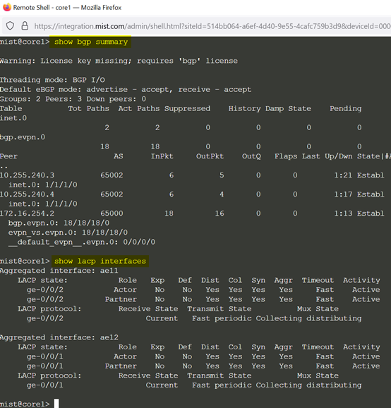
If that is not the case review the confirmation rendered that should be on the Switch.

The config should have such statements as example
.
set protocols bgp group evpn_underlay type external
set protocols bgp group evpn_underlay local-as 65001
set protocols bgp group evpn_underlay multipath multiple-as
set protocols bgp group evpn_underlay authentication-key $9$zLF8ntuIEcMLxCtNdbwaJ69CABISyKx-Vtu7-dVY2TzF3tucylW87levL7NY2fTQF39p0Bcre0OLx7-2g/CA0EcM8X-dsuOclvWx7P5TQ69u0ISyK0OEylK8Ldbs4Uj5QF39AQzSrvMN-Hq.Pfzp0ByevEhgoZGiHtu0OhSvMX-ds8LHqf5F3tuOIRS
set protocols bgp group evpn_underlay family inet unicast
set protocols bgp group evpn_underlay bfd-liveness-detection minimum-interval 350
set protocols bgp group evpn_underlay bfd-liveness-detection multiplier 3
set protocols bgp group evpn_underlay log-updown
set protocols bgp group evpn_underlay export evpn_underlay_export
set protocols bgp group evpn_underlay import evpn_underlay_import
set protocols bgp group evpn_underlay neighbor 10.255.240.4 peer-as 65002
set protocols bgp group evpn_underlay neighbor 10.255.240.3 peer-as 65002
set protocols bgp group evpn_overlay type internal
set protocols bgp group evpn_overlay local-address 172.16.254.1
set protocols bgp group evpn_overlay local-as 65000
set protocols bgp group evpn_overlay multipath
set protocols bgp group evpn_overlay authentication-key $9$zLF8ntuIEcMLxCtNdbwaJ69CABISyKx-Vtu7-dVY2TzF3tucylW87levL7NY2fTQF39p0Bcre0OLx7-2g/CA0EcM8X-dsuOclvWx7P5TQ69u0ISyK0OEylK8Ldbs4Uj5QF39AQzSrvMN-Hq.Pfzp0ByevEhgoZGiHtu0OhSvMX-ds8LHqf5F3tuOIRS
set protocols bgp group evpn_overlay family evpn signaling
set protocols bgp group evpn_overlay log-updown
set protocols bgp group evpn_overlay bfd-liveness-detection minimum-interval 1000
set protocols bgp group evpn_overlay bfd-liveness-detection multiplier 3
set protocols bgp group evpn_overlay bfd-liveness-detection session-mode automatic
set protocols bgp group evpn_overlay neighbor 172.16.254.2
set protocols bgp group evpn_overlay cluster 1.0.0.1.
.
If those are not local on the Switch then enforce a configuration sync as it might help a well.

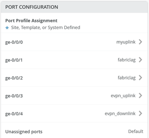
Attach Port Profiles to Ports on Access Switches
As a reminder these are the Links we do configure in this step.

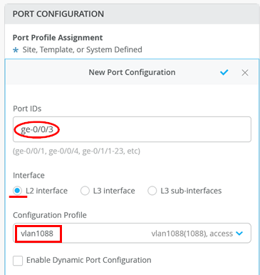
Go to Access1 Switch and attach Port profile “vlan1099” to Port ge-0/0/3
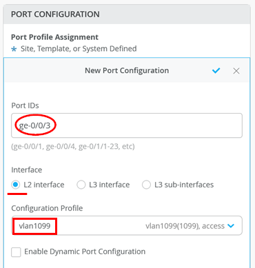
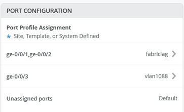
The following should be configured now
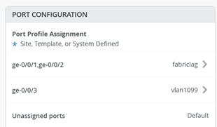
“Save” your Switch configuration.
Go to Access2 Switch and attach Port profile “vlan1088” to Port ge-0/0/3
The following should be configured now
“Save” your Switch configuration.
Configure WAN-Router ESI-LAG
As a reminder these are the Links we do configure in this step.
Review under Port Profiles the Switch Template created Profile named “myuplink” make sure all VLANs are trunked there.
Go to core1 Switch and configure the following Port configuration:
Port IDs=ge-0/0/0
Interface=L2 Interface
Configuration Profile=myuplink
Port Aggregation=Enabled
AE Index=0
ESI-LAG=Enabled
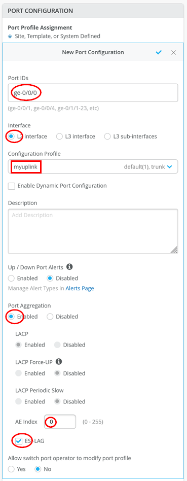
The following should be configured now
“Save” your configuration
REPEAT THE SAME CONFIGURATION ON CORE2 SWITCH!
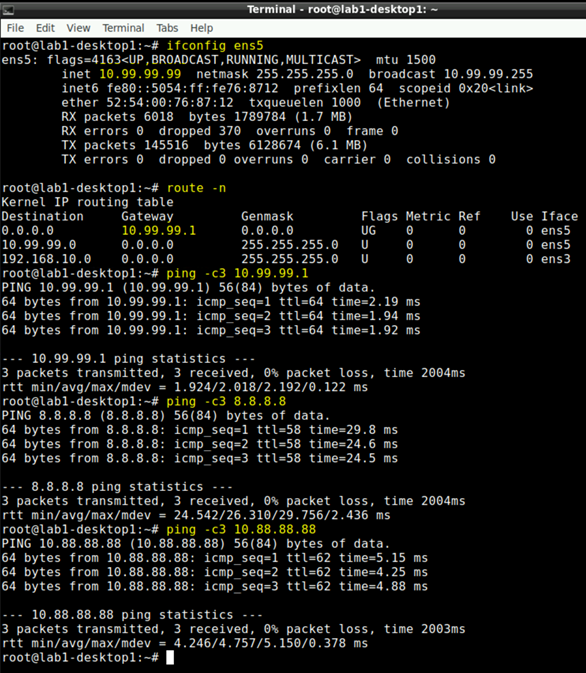
Test Fabric traffic
Go via Apache guacamole to the decktop1 VM of Lab1 and open a local shell. Try the following tests.
# to review the interface ens5 has the IP-Address 10.99.99.99 do
ifconfig ens5

# to review that 10.99.99.1 (VGA Fabric) is the default GW
route -n

# ping the local Gateway of the Fabric
ping -c3 10.99.99.1

# ping the Internet to ensure Traffic flows via WAN-Router
ping -c3 8.8.8.8

# ping the desktop 2 VM in the other VRF and Switch. Traffic has to flow via WAN-Router.
ping -c3 10.88.88.88
You should see similar results like the ones below.